Cortex-M3 (NXP LPC1788)之IIC应用--PCA9532进行IO扩展和LED亮度控制

做为从设备,他的8位地址的高四位固定为1100,最低位为数据的方向位,剩下的3位有硬件连线确定他的地址。PCA9532共有10个寄存器来配置他的输出状态。
本文引用地址:https://www.eepw.com.cn/article/201611/318456.htm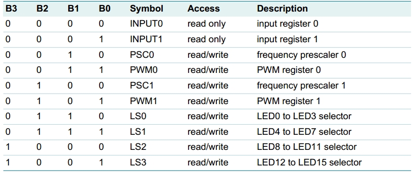
其中INPUT0 INPUT1在管脚配置成普通IO时候用于读入IO脚的状态。PSC0 PWM0 PSC1 PWM1用于设置两路PWM波的周期和占空比。LS0~LS3用于选择每个管脚的功能,包括通用LED OFF、LED ON、 PWM0、 PWM1。
知道了需要配置的寄存器,那怎么通过I2C通信来配置这几个寄存器呢?当LPC1788发出PCA9532的地址得到应答后,需要发送一个字节的数据用于配置控制寄存器,他们第四位为B3~B0位,比如发送的字节第4位为0,即B3~B0为0则他接下去收到的数据用来配置INPUT0。配置寄存器的第4位为AI,即autoincrease,表示接收到一个字节的配置数据后,是否自动的将B3~B0加1,方便配置下一个表中的寄存器。
开发板上的PCA9532的电路图如下
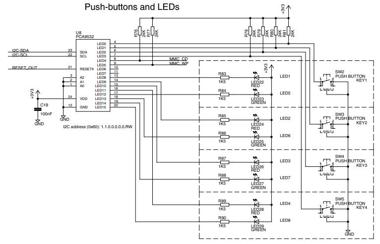
程序中配置LED0~7为GPIO用于检测按键,LED8~LED11配置成PWM输出,将LED RED做出渐亮渐暗的效果,LED12~LED15根据按键值设置成LED ON 或LED OFF。按键值读取PCA9532的INPUT0得到。程序如下
- #definePCLK60000000
- #defineI2C0SCK100000
- #definePCA9532_ADDRESS0x60
- #definerI2C0CONSET(*(volatileunsigned*)(0x4001C000))
- #definerI2C0CONCLR(*(volatileunsigned*)(0x4001C018))
- #definerI2C0STAT(*(volatileunsigned*)(0x4001C004))
- #definerI2C0DAT(*(volatileunsigned*)(0x4001C008))
- #definerI2C0SCLH(*(volatileunsigned*)(0x4001C010))
- #definerI2C0SCLL(*(volatileunsigned*)(0x4001C014))
- #definerIOCON_P0_27(*(volatileunsigned*)(0x4002C06C))
- #definerIOCON_P0_28(*(volatileunsigned*)(0x4002C070))
- #definerPCONP(*(volatileunsigned*)(0x400FC0C4))
- unsignedcharconfig[11],read_data[1];
- voidI2C0_Init()
- {
- rIOCON_P0_27=(rIOCON_P0_27&(~0x7))|0x1;//I2C0_SDA
- rIOCON_P0_28=(rIOCON_P0_28&(~0x7))|0x1;//I2C0_SCL
- rPCONP|=0x1<<7;//I2C0PowerEnable
- rI2C0SCLH=PCLK/I2C0SCK/2;//setI2C0frequency100khz
- rI2C0SCLL=PCLK/I2C0SCK/2;
- rI2C0CONSET|=0x1<<6;//I2C接口使能
- rI2C0CONCLR=0x1<<3|0x1<<5;//清除SISTA
- }
- unsignedcharI2C0_Start()
- {
- rI2C0CONCLR=0x1<<3;//清除SI标志
- rI2C0CONSET|=0x1<<5;//置位STA进入主发送模式
- while(!(rI2C0CONSET&(0x1<<3)));//起始条件发送完成
- rI2C0CONCLR=0x1<<5;//清除STA标志
- return(rI2C0STAT&0xF8);
- }
- voidI2C0_Stop()
- {
- rI2C0CONCLR=0x1<<5;//清除STA标志
- rI2C0CONSET|=0x1<<4;//发送STO标志
- rI2C0CONCLR=0x1<<3;//清除SI标志
- }
- unsignedcharI2C0_SentByte(unsignedchardata)
- {
- rI2C0DAT=data;
- rI2C0CONCLR=0x1<<3;//清除SI标志
- while(!(rI2C0CONSET&(0x1<<3)));//发送完数据得到了应答
- return(rI2C0STAT&0xF8);
- }
- unsignedcharI2C0_GetByte(unsignedchar*data,unsignedcharack_flag)
- {
- if(ack_flag)
- {
- rI2C0CONSET|=0x1<<2;//主接收模式,接收到一个字节返回应答
- }
- else
- {
- rI2C0CONCLR=0x1<<2;//主接收模式,接收最后一个字节时,不返回应答
- }
- rI2C0CONCLR=0x1<<3;//清除SI标志
- while(!(rI2C0CONSET&(0x1<<3)));//发送完数据得到了应答
- *data=(unsignedchar)rI2C0DAT;
- return(rI2C0STAT&0xF8);
- }
- intI2C0_MasterTransfer(unsignedcharslave_address,unsignedchar*transfer_data,unsignedinttransfer_count,
- unsignedchar*receive_data,unsignedintreceive_count)
- {
- unsignedcharstatus;
- unsignedinti;
- status=I2C0_Start();
- while(status!=0x08);
- status=I2C0_SentByte(slave_address<<1);
- while(status!=0x18);
- for(i=0;i
- {
- status=I2C0_SentByte(*(transfer_data+i));
- while(status!=0x28);
- }
- if(receive_data!=(void*)0&&receive_count!=0)
- {
- //进入主接收模式
- status=I2C0_Start();
- while(status!=0x10);
- status=I2C0_SentByte((slave_address<<1)|0x1);
- while(status!=0x40);
- for(i=0;i
- {
- if(i
- {
- status=I2C0_GetByte(receive_data,1);
- while(status!=0x50);
- }
- else
- {
- status=I2C0_GetByte(receive_data,0);
- while(status!=0x58);
- }
- receive_data++;
- }
- }
- I2C0_Stop();
- return1;
- }
- voidPCA9532_Config()
- {
- config[0]=0x1<<4;//读写控制寄存器后低四位自动增加
- config[1]=0;//input0
- config[2]=0;//input1
- config[3]=0;//PSC0PWM0的周期6.5ms
- config[4]=0;//PWM0PWM0占空比设置成0%
- config[5]=0;//PSC1PWM1的周期为6.5ms
- config[6]=0;//PWM1PWM1占空比设置成0%
- config[7]=0;//LS0
- config[8]=0;//LS1LED0~7设置成GPIOS
- config[9]=0xFA;//LS211111010,LED8,9->blinksPWM0;LED10,11->blinksPWM1
- config[10]=0;//LS3LED12~LED15,LEDoff
- }
- intmain(void)
- {
- unsignedcharflag=1,data=0;
- unsignedinti;
- I2C0_Init();
- PCA9532_Config();
- while(1)
- {
- I2C0_MasterTransfer(PCA9532_ADDRESS,config,sizeof(config),0,0);
- I2C0_MasterTransfer(PCA9532_ADDRESS,&data,1,read_data,1);
- if(flag)
- {
- config[4]++;
- config[6]++;
- }
- else
- {
- config[4]--;
- config[6]--;
- }
- if(config[4]==255||config[4]==0)
- {
- flag=!flag;
- }
- for(i=0;i<4;i++)
- {
- if(read_data[0]&(0x1<
- {
- config[10]&=~(0x3<<(i*2));
- }
- else
- {
- config[10]|=(0x1<<(i*2));
- }
- }
- }
- }
程序调试过程中遇到如下问题,要注意:
1,I2C控制清除寄存器为只读,因此不能进行|=操作,否则状态寄存器的值异常。不知道为什么不是产生异常复位,之前EEPROM也对只读寄存器进行该操作会产生系统异常进入异常中断。
2,在主发送模式切换到主接收模式的过程中,一定要先清除SI标志。开始没注意,发送重复起始表示后的状态一直是0x28,把这个重复起始标志单数据发送?


评论