IRIRS29751S120W正负30VD类音放电源解决方案

The IRS2795(1,2) is a self oscillating half-bridge driver IC for DC-DC resonant converter applications, especially the LLC resonant half-bridge converter. The frequency and dead time can be programmed externally using two external components. The IC offers over current protection using the on state resistance of the low-side MOSFET. The IC can be disabled by externally pulling the voltage at the CT/SD pin below its enable voltage threshold.
IRS2795(1,2)主要特性:
· Simple primary-side control solution for fixed and variable frequency DC-DC resonant converters.
· Max 500kHz per channel output with 50% duty cycle
· Floating channel bootstrap operation up to +600Vdc
· Programmable minimum and maximum switching frequency
· Programmable soft start frequency and soft start time
· Programmable dead time
· Micropower start-up ultra low quiescent current
· Over-current protection using low side MOSFET Rds(on)
· User initiated micropower “Sleep mode”
· Under-voltage Lockout
· Simple design with minimal component count.
· Lead-free
IRS2795(1,2)典型应用:
· LCD PDP TV
· Telecom SMPS, PC SMPS
· Home Audio Systems
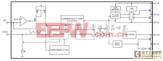
图1.IRS2795(1,2)方框图
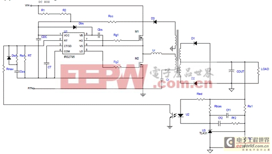
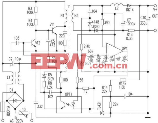
图2.IRS2795(1,2)典型应用电路图
D类音频放大器+/-30V电源参考设计
The evaluation board consists of a front-end AC-DC rectifier stage cascaded with a half-bridge resonant DC/DC converter with +/-30V output voltage rails.
The front end is a conventional pi type EMI filter, followed by bridge rectifier stage. Two 200V/680uF bulk capacitors are connected in series to provide stable DC bus voltage. The rectifier can be configured as full bridge rectifier for 220Vac input, or voltage doubler rectifier for 110Vac input.
The downstream converter is a multi-resonant half bridge LLC converter whose control is implemented with the IRS27952 controller HVIC (U101 on the control board). The controller drives the two half-bridge MOSFETs with a 50 percent fixed duty cycle with pre-defined dead-time. Output voltage regulation is achieved by changing the switching frequency according to the feedback signal.
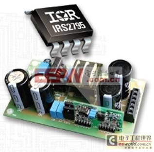
图3.+/-30V电源参考设计外形图
+/-30V电源参考设计技术指标:
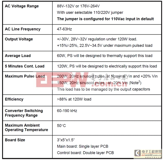
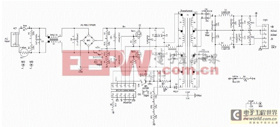
图4.+/-30V电源参考设计主板电路图
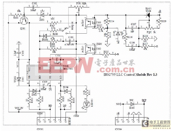
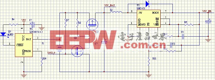
图5.+/-30V电源参考设计控制板电路图
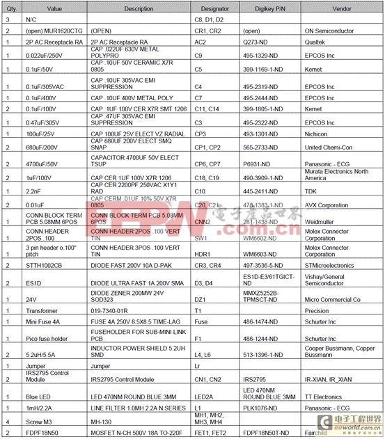
主板材料清单:

控制板材料清单:
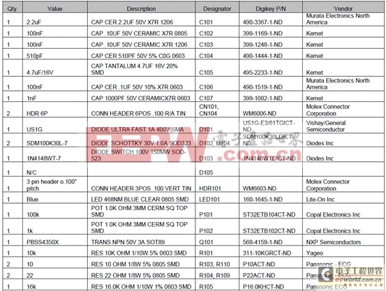
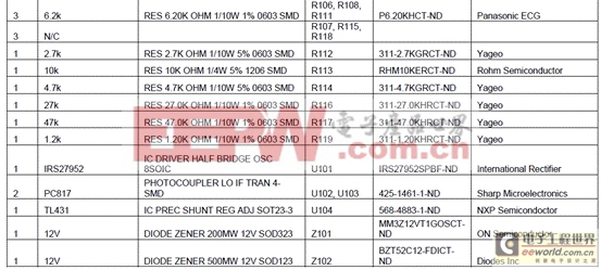
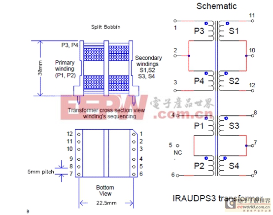
图6.谐振变压器绕组电路图
谐振变压器绕组特征表:

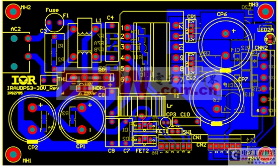
图7.主板布局图(单层PCB)
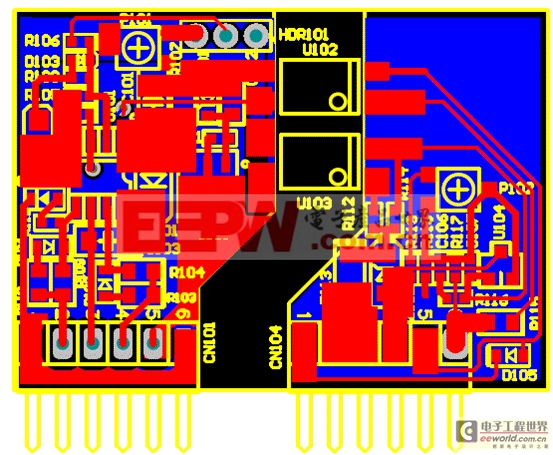
图8.控制板布局图(双层PCB)
详情请见:
http://www.irf.com/product-info/datasheets/data/irs27951s.pdf
和
http://www.irf.com/technical-info/refdesigns/iraudps3.pdf


评论