手机耳机接口插拔识别方案

The audio jack has become standard in smart phone applications.These jacks allow the user to either plug a headset with a microphone (4 pole) or stereo headphones (3 pole).The current system design allows the mobile phone to detect between 3 or 4 pole and Send/End key, but the design has inherent issues with power, detection errors, and pop-n-click.These issues in functionality and audio quality can result in a poor user experience.Fairchild’s new audio jack detection switches provide an interface between the audio jack, baseband processor, and microphone preamp.These new devices automatically detect what is plugged into the audio jack, resolve software issues, drastically reduce system current, reduces PCB space, and eliminate pop-n-click caused by the microphone bias.
本文引用地址:https://www.eepw.com.cn/article/201706/351154.htmThe Current Solution:
The current audio jack detection solution is designed with discrete components, typically a comparator with supporting resistors and capacitors (see Figure 1).This design has inherent flaws, these flaws result in user interface issues wasted current, and audio pop-n-click.The comparator in the circuit is utilized for two functions; one to detect between a 3 pole (stereo headphones) or 4 pole (headset with microphone) audio plug, two detect a Send/End key push.If a 3 pole plug is inserted the mic line is pulled to GND, the comparator outputs a Low to the baseband.When a 4 pole plug is connected the mic line typically is 1.8V with no Send/End key press.When the Send/End key is pressed it shorts the mic line to ground and the comparator outputs a s Low to the baseband.This causes a fundamental issue if a 4 pole headset is connected while pushing the Send/End key the baseband registers a 3 Pole jack, and the system may never recover.Additionally, this design increases current consumption in two significant areas.The resistor divider used to set the comparators voltage reference is connected directly to the supply, which continuously drains about 28μA (I2 on Figure 1) even when there is no audio plug.The Mic bias is not isolated based on the system settings.If a 4 pole plug is connected and the mic is not required the Mic bias drains >500uA (I1 on Figure 1) through the RMIC and Microphone.Not gating the Mic bias also creates a pop-n-click issue.The mic line is typically the fourth pole in the audio jack, when the plug is inserted or removed the left and right speaker terminals scrape across the mic bias, causing pop-n-click.All of these issues cause increased system design software time to try to mitigate them, and a poor user experience.
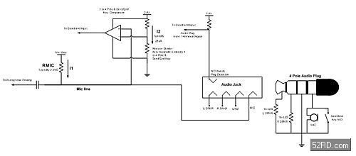
Figure 1 – Current Audio Jack Detection Design
Audio Jack Detection Switches:
Mobile phone manufacturers increased scrutiny on the user experience has resulted in a new device function; audio jack detection switches.Devices such as the FSA8008 interface between the audio jack, baseband, mic preamp (Figure 2).These detection switches focus on resolving the issues of the current solution, while providing further features such as: board space savings, increased ESD performance, simple baseband interfaces, and automatic reset.

Figure 2 – Audio Jack Detection Switch Solution
Solve Stuck Send/End Key Issue:
When a user plugs in a headset and holds the Send/End key the phone errors and recognizes a 4 pole headset as a 3 pole stereo headphones.In this mode the mic preamp will be muted or off and the headset microphone will not function.Further, the phone will never recover from this state creating a poor user experience.Audio jack detection switches like the FSA8008 resolve this issue by continuously monitoring the mic bias line voltage when a3 pole jack is detected.If a 3 pole plug is ever detected, proprietary circuitry in the FSA8008 close the switch connecting the Mic bias voltage to the 4th pole of the audio jack for a short duration.If the mic line voltage equals ground a 3 pole is still connected, but if the mic line voltage is above 200mV it is a 4 pole headset.The device will recognize this change and output the update on the JPOLE pin to the baseband.The phone will recover from the error, and the microphone will be functional.This solution solves poor user experience by automatically correcting the error and updating the system.
Reduce System Current:
The current system design is not a low power solution; it wastes power in two instances.The current leakages occur with the comparator voltage reference (I2 = 28uA in Figure 1) and when the headset is connected and the microphone is not required (I1 >500uA in Figure 1).Detection switches significantly reduce system current by consolidating the comparator, voltage reference, switch, and logic into one device.In the current solution (Figure 1) the comparator and voltage reference alone represent 48μA (comparator = 20μA + voltage reference =28μA).The total worst case, max current consumption of a detection switch like the FSA8008 is 25uA, saving almost half the current of the comparator and voltage reference alone.Further, the detection switch detects when the audio plug is inserted or removed, when the plug is removed the detection switch automatically enters a low power state of 3μA max.
Understanding the mobile phone’s current operation can further reduce current.For example in MP3 mode the Send/End key can be used for play and pause, but the microphone is not required.In the current solution, the mic line bias is required to identify the Send/End key push.The mic line bias creates leakage current greater than 500uA through RMIC and the microphone.Audio jack detection switches can reduce this current by monitoring for a Send/End key push.Human interfaces like the Send/End key input only require hundreds of milliseconds of accuracy. This allows the detection switch to only need to monitor the Send/End key for a short duration of time.To monitor the Send/End key the internal switch is closed, the mic line bias is measured for a Send/End key push or not.If a key push is detected the Send/End key is debounced and the baseband is notified.If no key push is detected, the internal switch is opened.The duty cycle of this monitor is 90 / 10, saving 90% of the system power over the current solution.
Eliminate Pop-n-Click caused by Microphone Bias
Depending on the design the mic line maybe connected to the 3rd or 4th pole of the audio jack.In either case if the mic bias voltage is present when the audio plug is inserted or removed pop-n-click will be heard, creating a poor user experience.The left and right speakers are connected to the 1st and 2nd poles respectfully and when inserting or removing the plug these poles will scrape past the mic bias voltage causing the pop-n-click.Audio jack detection switches like the FSA8008 have all the components to fully eliminate this issue.The device includes the audio plug insert or removal detection pin (J_DET), the switch to isolate the mic line bias, and the debounce circuitry.When the audio plug is inserted, the J_DET pin detects the connection and the internal logic debounces the manual connection.After the debounce is completed, the baseband will be notified of the connection and the internal switch can be closed.When the audio plug is removed the detection switch must react quickly to isolate the mic line bias before the R SPKR (Right Speaker) contacts the GND (ground) internal to the audio jack.In this case the detection switch recognizes the audio plug removal, quickly debounces the connection, and opens the switch.Integrating these three features into the detection switch allows the devices to fully resolve the pop-n-click from the mic bias issue.
The new device type of audio jack detection devices, resolve inherent issues with the current system solution.These devices can improve the user experience and system design by eliminating pop-n-click, reducing leakage current, and resolving detection errors.


评论