Introduction to the DS8500 HART modem

-- ======================================================================= -->-- CONTENT: DB HTML -->-- ======================================================================= -->
Introduction
This application note introduces the DS8500 single-chip modem for HART® communication. This document should be used in conjunction with the DS8500 data sheet. While the specific requirements for an application can vary, the reference design shown here is a basic example for implementing a process-control circuit.HART overview
Highway Addressable Remote Transducer (HART) communication is a commonly used mode of transmission for digital signals that are superimposed on the analog signal of a 4C20mA current loop. The HART protocol is based on the phase continuous frequency shift keying (FSK) technique. Bit 0 is modulated to a 2200Hz sinusoidal signal, and bit 1 is modulated to a 1200Hz sinusoidal signal with a baud rate of 1200bps. These two frequencies can easily be superimposed on the analog current-loop signal, which is in the range of DC to 10Hz, without affecting either signal. This unique nature of the HART protocol enables simultaneous analog and digital communication on the same wire.DS8500 HART modem
The DS8500 is a HART modem that provides phase-continuous FSK modulation and demodulation for process-control applications. This device is a feature-rich low-power modem that satisfies the physical layer specifications set by the HART Communication Foundation. The DS8500 has many features that allow the user to easily and effectively design a process-control system that requires a HART modem.- Reliable signal detection
- Few external components
- Sinusoidal output signal
- Low power consumption
- Standard 3.6864MHz crystal
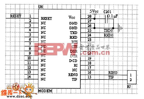
Figure 1 shows a top-level block diagram of the DS8500 in an intelligent process transmitter. The design highlights the interface between the HART modem and other external ICs.
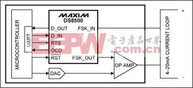
Figure 1. An intelligent process transmitter features the DS8500 HART modem communicating with a system microcontroller.
Basic DS8500 operation
Clock
The DS8500 requires a 3.6864MHz clock as an input source with ±1% accuracy to guarantee proper operation. Figure 2 shows a typical circuit for clock source. When XCEN is set high, the user can drive an external clock directly onto the XTAL1 pin. If an external 3.6864MHz crystal is desired, XCEN should be set low and the crystal needs to be connected between XTAL1 and XTAL2.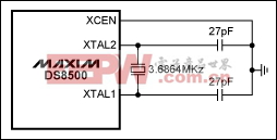
Figure 2. Crystal connection for the DS8500.
Microcontroller interface
The HART protocol requires signals to be communicated in a specific 11-bit UART format: a start bit, 8 data bits, one parity bit, and a stop bit. The modulator and the demodulator blocks of the DS8500 need to interface with a microcontroller UART to satisfy the protocol requirement.In demodulator mode, the DS8500 expects a valid UART start signal to synchronize the data communication. The interface between the HART modem and the microcontroller is also shown in Figure 1. Referring back to Figure 1, the microcontroller must contain the HART software stack required for communication. D_IN is the digital-signal data input to the DS8500 which will modulate it to an FSK_OUT signal. D_OUT is the digital-signal data output from the DS8500 that has been demodulated from an FSK_IN signal. RTS receives the microcontroller's request to initiate the demodulate (Rx) or modulate (Tx) mode of the modem.
Active-low RST provides a reset to the DS8500 and ensures that all the internal registers and filters start from a known default value. OCD is a carrier-detect signal that determines an FSK signal with a valid amplitude at the input of the demodulator. A logic high on OCD indicates that the FSK_IN signal amplitude is greater than 120mV; a logic low indicates that the FSK_IN signal amplitude is less than 80mV or that there is no carrier signal. Optionally, the microcontroller can provide a 3.6864MHz clock to the DS8500.
Modulator waveform
Figure 3 shows the DS8500 in modulate mode where D_IN is the input to the modem and FSK_OUT is the modulated output. The data is provided in an 11-bit UART format.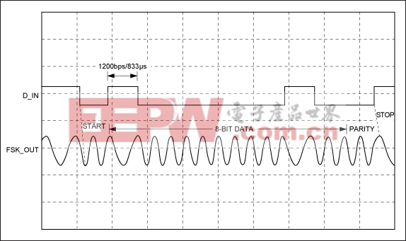
Figure 3. Modulator waveform.
Demodulator waveform
Figure 4 shows the DS8500 in demodulate mode where FSK_IN is the input to the modem and D_OUT is the output to the UART.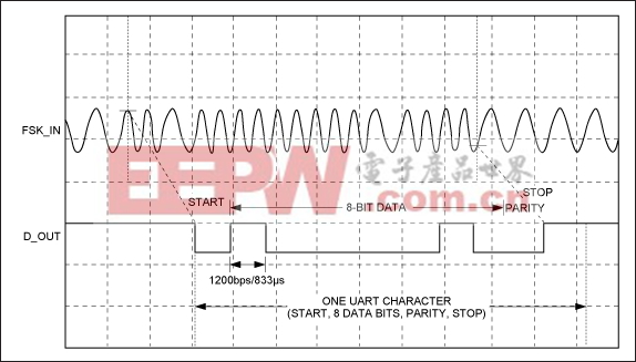
Figure 4. Demodulator waveform.


评论