Introduction to the DS8500 HART modem
External filters
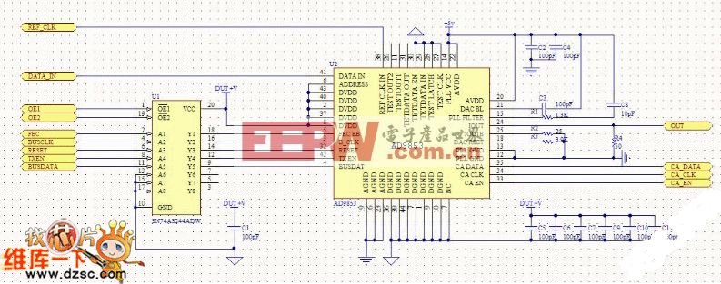
Due to the digital nature of DS8500 and its built-in digital filters, the number of external passive components required for modem operation is greatly reduced.Figure 5 shows the few external components needed on the receive and transmit sides. The demodulator in DS8500 requires just a simple lowpass filter with a cutoff frequency of 10kHz (R3, C3) and a highpass filter with a cutoff frequency of 480Hz (C2, R2) to separate the HART signal from the analog signal and interferences. The resistor-divider formed by R1 and R2 provides an input bias voltage of VREF/2 to the DS8500's receive-side circuitry. The RC values shown below are just an example; a different set of RC values can be used, if the cutoff frequencies of lowpass and highpass filters are met.
Together these external components and the internal filters reject the low-frequency analog signals and prevent them from compromising digital reception. In addition, high-frequency components are also attenuated to prevent interference above the HART extended frequency band.
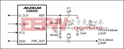
Figure 5. Receive/transmit side external components.
DS8500 as slave or master
The DS8500 modem can be used in either the slave side or the master side of HART communication. Typically, on the slave side the HART modem is part of the intelligent process transmitter unit; on the master side the modem is part of the HART master modem cable that connects the central control unit or the handheld unit to the current loop. Figure 6 shows the interface between master, slave, and current loop.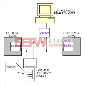
Figure 6. HART devices connections.
Figure 7 shows a HART slave using DS8500 circuitry and the top-level blocks necessary for an intelligent process transmitter. A temperature process transmitter serves as an example for this circuit. The sensor on the process transmitter measures the system temperature in current or voltage and then passes the data to the ADC. The ADC, in turn, converts these analog signals to digital equivalents for the microcontroller to process. The microcontroller provides remote memory along with computation power. The microcontroller typically hosts the HART stack and is responsible for the protocol implementation; it also processes the digital data from the HART modem. Microcontroller capabilities can also be used for sensor calibration, linearization and signal conditioning. The DAC is primarily responsible for driving the current loop.
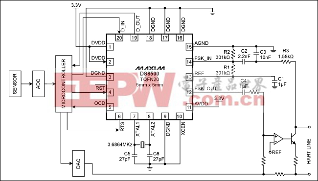
Figure 7. DS8500 on the slave side of HART communication. D_IN receives data from the microcontroller's UART. D_OUT transmits data to the UART. Active-low RST is the DS8500 reset. OCD is a carrier-detect signal that determines a FSK signal with a valid amplitude at the input of the demodulator.
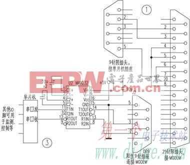
On the master side, the DS8500 can be part of the master modem that resides either on the central control unit or the handheld HART communicator. Figure 8 shows the master-side configuration. In this case, the DS8500 communicates to the PC through an RS-232 serial port. The HART protocol is usually supported by software that can be installed on the computer.
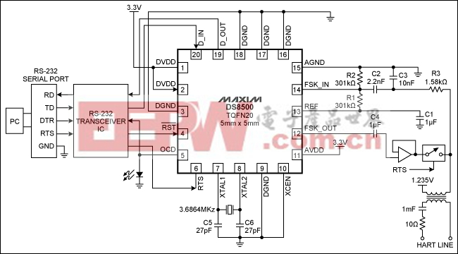
Figure 8. DS8500 on the master side of HART communication. D_IN receives data from the microcontroller's UART. D_OUT transmits data to the UART. Active-low RST is the DS8500 reset. OCD is a carrier-detect signal that determines a FSK signal with a valid amplitude at the input of the demodulator.
Maxim cannot assume responsibility for use of any circuitry other than circuitry entirely embodied in a Maxim product. No circuit patent licenses are implied. Maxim reserves the right to change the circuitry and specifications without notice at any time.


评论