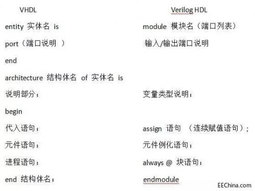
汽车尾灯VHDL设计

汽车尾灯VHDL设计
标签/分类:
本文引用地址:https://www.eepw.com.cn/article/197462.htm1.系统设计要求
用6个发光管模拟6个汽车尾灯(左右各3个),用4个开关作为汽车控制信号,分别为:左拐、右拐、故障和刹车。
车匀速行驶时,6个汽车尾灯全灭;右拐时,车右边3个尾灯从左至右顺序亮灭;左拐时,车左边3个尾灯从右至左顺序亮灭;故障时车6个尾灯一起明灭闪烁;刹车时,6个尾灯全亮
2.系统设计方案
根据系统设计要求,采用自顶向下设计方法,顶层设计采用原理图设计,它由主控模块、左边灯控制模块和右边灯控制模块三部分组成。
3参考VHDL源程序
(1) 主控制模块
说明:此程序为系统主控制模块。当左转时,lft信号有效;右转时,rit信号有效;当左右信号都有效的时,lr有效。
libraryieee;
useieee.std_logic_1164.all;
entitykzis
port(left,right:instd_logic;
lft,rit,lr:outstd_logic);
endkz;
architecturekz_arcofkzis
begin
process(left,right)
variablea:std_logic_vector(1downto0);
begin
a:=leftright;
caseais
when00=>lft='0';
rit='0';
lr='0';
when10=>lft='1';
rit='0';
lr='0';
when01=>rit='1';
lft='0';
lr='0';
whenothers=>rit='1';
lft='1';
lr='1';
endcase;
endprocess;
endkz_arc;
(2)左边灯控制模块
说明:此模块的功能是当左转时控制左边的3个灯,当左右信号都有效时,输出为全“1”。
libraryieee;
useieee.std_logic_1164.all;
entitylftais
port(en,clk,lr:instd_logic;
l2,l1,l0:outstd_logic);
endlfta;
architecturelft_arcoflftais
begin
process(clk,en,lr)
variabletmp:std_logic_vector(2downto0);
begin
iflr='1'then
tmp:=111;
elsifen='0'then
tmp:=000;
elsifclk'eventandclk='1'then
iftmp=000then
tmp:=001;
else
tmp:=tmp(1downto0)'0';
endif;
endif;
l2=tmp(2);
l1=tmp(1);
l0=tmp(0);
endprocess;
endlft_arc;
(2) 右边灯控制模块
说明:此模块的功能是控制右边的3个灯,与上面模块相似。
libraryieee;
useieee.std_logic_1164.all;
entityritais
port(en,clk,lr:instd_logic;
r2,r1,r0:outstd_logic);
endrita;
architecturerit_arcofritais
begin
process(clk,en,lr)
variabletmp:std_logic_vector(2downto0);
begin
iflr='1'then
tmp:=111;
elsifen='0'then
tmp:=000;
elsifclk'eventandclk='1'then
iftmp=000then
tmp:=100;
else
tmp:='0'tmp(2downto1);
endif;
endif;
r2=tmp(2);
r1=tmp(1);
r0=tmp(0);
endprocess;
endrit_arc;


评论