Diagnose LEDs by monitoring the switch-mode du

The forward voltage (VF) of high-brightness LEDs (HB LEDs) is often monitored to assess the health of the LED. Big changes in VF can indicate deterioration or even a complete failure of one or more LEDs connected in series.
For several LEDs in series, the sum of their VF voltages can go to 40V or more, and if not referenced to ground, that VF sum requires a differential measurement. As a third challenge (in addition to high voltage and differential measurement), HBLEDs are often dimmed using pulse-width modulation (PWM). If so, you can't measure VF during the low portion of the PWM duty cycle, when the LEDs are not illuminated and VF is not present. For a hysteretic buck LED driver (MAX16820) driving three LEDs in series (Figure 1), you must measure the anode and cathode voltages of the string when DIM is high.

Figure 1. Standard driver circuit for HB LEDs.
To avoid the need for a differential high-voltage measurement, you can take the indirect approach of measuring the duty cycle at the DRV pin. For this particular LED driver, a first-order estimate of forward voltage for the LED string is VF = D × VIN, where D represents an internal duty cycle produced in the IC's switchmode section (not to be confused with the duty cycle at DIM). The DRV signal is referenced to ground and limited to VCC (5V). That condition allows the use of low voltage ADCs or comparators, which in turn can be powered by the LED driver's VCC output (10mA maximum).
Figure 2 shows how to detect a short-circuited LED with the aid of a comparator (MAX9141). Filter R1C1 converts the AC PWM signal at DRV to a DC voltage (VD) proportional to D × VCC. VD should be sampled when its value is greater than (perhaps) 90% of its steady-state value, which requires a period of at least 2.3R1C1. Because the comparator's Latch Enable (LE) latches the output when LE is low, LE should assert not earlier than 2.3R1C1 after DIM goes high. R2C2 in combination with D2 ensures that LE de-asserts immediately after DIM goes low. The R2C2 value is higher than R1C1, so the comparator enables when the input signal reaches at least 90% of its steady-state value. D2 discharges C2 immediately after DIM goes low, which latches the output as soon as the LEDs go off.

Figure 2. Adding this comparator circuit to the Figure 1 circuit provides detection of shorted LEDs.
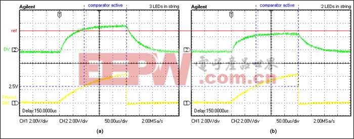
Because Ref is lower than D × VIN, the comparator output is normally low. If an LED fails shorted, its forward voltage drops and causes the duty cycle at DRV to drop. VD then drops below Ref, causing the comparator output to go high, indicating a shorted LED. Because the output latches when DIM goes low, the error signal remains asserted even when the LEDs are off. Figure 3 shows the filtered DIM and DRV signals for normal operation vs. a shorted-LED condition.


评论