How to build a simple, interactive digital vol
-- ======================================================================= -->-- CONTENT: DB HTML -->-- ======================================================================= -->Download an example project with the code described in this application note.
Introduction
The MAXQ2010-KIT showcases the MAXQ2010 microcontroller. The kit has a versatile board with the following features:- Two pushbuttons for reset and interrupt lines
- One 5-way switch
- 19 exposed GPIO pins
- Eight ADC channels
- A photocell
- A thermistor
- An LCD screen
The MAXQ2010's integrated ADC accepts a voltage from 0V to 3.3V and translates it into a bit value from 0 to 4095 (12 bits of precision). The microcontroller then scales the value to a range from 0 to 3.3000 and writes it on the board's LCD. The application code repetitively samples all eight ADC channels and uses the 5-way switch to determine which channel to display.
Aside from the EV kit, no additional parts are required. Included in the EV kit is a limited version of the IAR Embedded Workbench® software. The full version of the software can be purchased from the IAR website. The sample application was written and compiled on version 2.20I.
Getting started
Set up the board according to the EV kit documentation. You should also install jumpers J30 and J31, which will connect the photocell (R17) to ADC input 6 (AN6) and connect the thermistor (R20) to ADC input 7 (AN7). You can also add voltages on ports 0C5, as long as the voltages stay within the 0V to 3.3V range.Next, run the IAR software. In the top left corner click File
 Open Workspace. Navigate to the directory containing the voltmeter project and open voltmeter.eww. The project settings will already be set up. To ensure that the JTAG is set to the correct COM port, right click on the bold-faced project name on the left side of the screen and select Options (Figure 1). Go to Categories, click JTAG under Debugger, and enter the COM port to which your programmer is connected (Figure 2). To check which COM port is being used, open Device Manager. The EV kit documentation details how to get there.
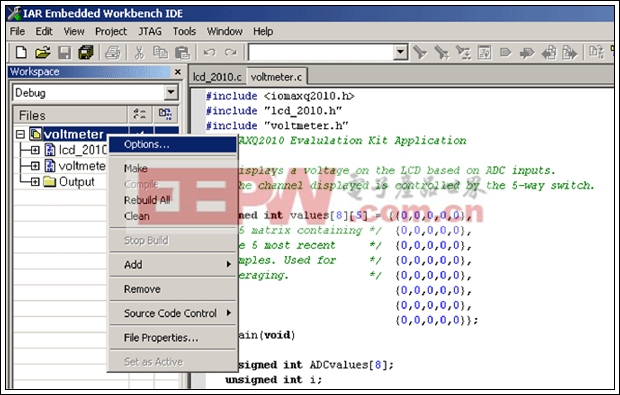
Figure 1. To verify that the JTAG is set to the correct COM port, start with the Options menu.
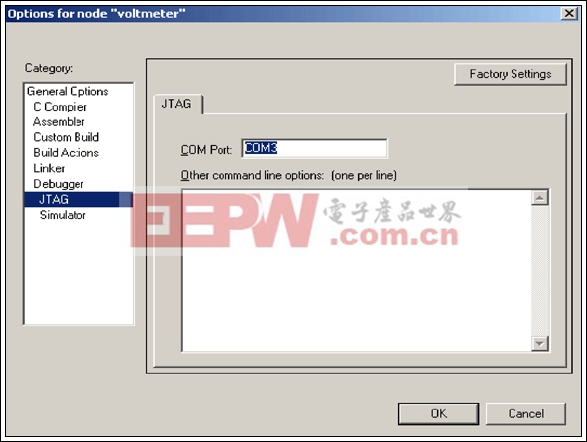
Figure 2. Find the JTAG option and enter the COM port to which your programmer is connected.
Next, click Debug on the far right side of the toolbar (Figure 3). This will compile, link, and program your board. The debug menu will be brought up momentarily. A green arrow will be pointing to the main function. Run the program by pressing F5 or clicking the button on the toolbar that looks like a flat piece of paper with three arrows above it.
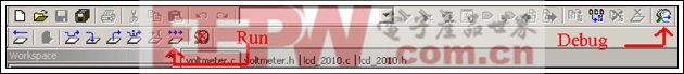
Figure 3. Use the Debug command to compile, link, and program your EV kit board.
Application results
Featured on the EV kit board are two analog inputs, the thermistor and photocell, which continuously output voltage signals. Both of these inputs are connected to ADC pins so their voltage can be measured. The sample application reads eight ADC values (on channels 0 through 7) at a time. The values are sent to a software lowpass filter that removes high-frequency noise. The selected ADC channel is displayed on the LCD. On the lower right-hand corner of the board is a switch. Pressing this switch down or to the right increments the ADC channel to be monitored. If the channel selected is greater than seven, the software selects channel zero instead. Conversely, pressing the switch up or to the left decreases the ADC channel; channel seven is monitored if the channel selected is less than zero. To display the current channel being monitored, press in the switch. To stop the ADC from sampling, hold the button SW3 down. While SW3 is held down, the channel can still be changed.After reset, the microcontroller displays the photocell voltage on channel six. The more light the cell receives, the lower the voltage is across it. Effectively, the voltage at the ADC pin is directly related to the amount of light present. This is because the photocell is part of the voltage-divider on AN6 (see Figure 4). In fluorescent lighting, the voltage will sit around 2V. If you shade the corner of the board that contains the cell, the voltage will drop a bit; completely covering the photocell with your finger will drop the voltage to approximately 0.5V. Removing your finger will return the voltage to 2V.
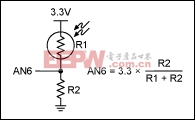
Figure 4. The voltage-divider and the equation that determines the voltage.


评论