单开关实现小型微处理器系统的双功能

价格低,易使用设计实现外围传感器|0">传感器的监控。
传统控制系统设计使用隔离开关控制电源和各种系统功能,但是给小型微处理器系统增加一些器件,能与系统开关结合成控制功能。例如,设计系统显示相对湿度和温度(参考文献1)。这个小型电池供电的系统需要微处理器可控的供能开关,可以用按钮实现。摄氏度显示到热力学温度的改变也可以用一个功能开关实现。从易使用和总投入的观点看,用单一开关结合这两个功能更有意义。
图1显示这个应用的电路。首先,R1使P沟道MOSFET Q1的栅-源极电压稳定在0V,使得Q1关闭。没有输入达到电压稳压器IC1,从而系统的微处理器IC2还仍然关闭。当操作者按下常闭瞬时接触按钮开关S1,电流通过R1和R2流到地,不断提高栅源极电压到足够打开Q1和为IC1和微处理器供能。电容C1使开关接触处弹起,不论使用者多迅速的按下和释放开关,都确保Q1状态足够长到使微处理器启动。此外,作为最后的任务,启动固件初始化系统的LCD,从而使操作者趋势保持供能开关处于位置上时间足够长,确保完全启动。
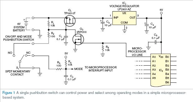
微处理器立即启动之后,开始执行固件并通过3V以上的N沟道MOSFET Q2门极电压传递到逻辑单元,打开Q2。接下来,Q2保持Q1开关打开,系统在软件控制下运行。如果操作者再次按下开关按钮,Q1仍然打开,微处理器继续运行,但是模型线被上拉。模型线驱动中断输入引脚,软件作为所存功能或访问包裹的多选择菜单来使用中断。适当的预编程时间间隔后,微处理器系统通过Q2的栅极被置于逻辑零而实现自我关闭。然后,Q2关闭Q1实现系统断电。
英文原文:
Single switch serves dual duty in small, microprocessor-based system
Low-cost, easy-to-use design allows monitoring of peripherals, sensors.
Steve Hageman, Windsor, CA; Edited by Brad Thompson and Fran Granville -- EDN, 3/30/2006
Traditional control-system designs use separate switches to control power and various system functions, but adding a few components to a small, microprocessor-based system can combine a control function with the system's on/off switch. For example, you can design a system to display relative humidity and temperature (Reference 1). This small, battery-powered system requires a microprocessor-controlled on/off power switch, which you implement with a pushbutton, and a function switch to change the display from degrees Celsius to degrees Fahrenheit, which you implement as a toggle switch. From ease-of-use and total- cost perspectives, combining these two functions in a single switch makes sense.
Figure 1 shows a circuit for this application. Initially, Q1, a P-channel MOSFET, is off because R1 holds Q1's gate-to-source voltage at 0V. No input reaches voltage regulator IC1, and, thus, the system's microprocessor, IC2, also remains off. When the operator presses the normally closed momentary-contact pushbutton switch, S1, current flows through R1 and R2 to gro
und, developing sufficient gate-to-source voltage to turn on Q1 and apply power to voltage regulator IC1 and the microprocessor. Capacitor C1 debounces the switch contact and ensures that Q1 remains on long enough to start the microprocessor, regardless of how quickly the user presses and releases the switch. In addition, as its final task, the start-up firmware initializes the system's LCD, thus reinforcing the operator's tendency to hold the power switch in its on position long enough to ensu
re full start-up.
Immediately after the microprocessor powers up, it begins executing its firmware and turns on Q2, an N-channel MOSFET, by delivering a logic one of more than 3V to Q2's gate. In turn, Q2 keeps Q1 switched on, and the system runs under software control. If the operator again presses the on/off button, Q1 remains on, and the microprocessor continues to run but pulls its mode line high. The mode line drives an interrupt input pin, and the software can use the interrupt as a toggling function or to access a wraparound, multiple-choice menu. After a suitable preprogrammed time interval, the microprocessor system turns itself off by placing a logic zero on Q2's gate. In turn, Q2 switches off Q1 to remove power from the system.
Reference
Hageman, Steve, Relative humidity/temperature meter, www.analoghome.com/projects/dewpointer.html.
英文原文地址:http://www.edn.com/article/CA6317068.html


评论