LED driver solution for MR16 and similar retrofit lamps

Introduction
This application note describes a proprietary solution that will drive LEDs off a 12VAC input for MR16 and similar retrofit lamps. This design can be used with both magnetic and electronic transformers. It is dimmable with leading-edge dimmers for magnetic transformers and with trailing-edge dimmers for electronic transformers. No electrolytic capacitors are required. This greatly extends the lifetime of an LED lamp, because electrolytic capacitors are typically the element of the system with the shortest lifetime.Solution specifications
- Input voltage: 12VAC
- Output LED power: 5W
- Number of output series LEDs: 3 to 4
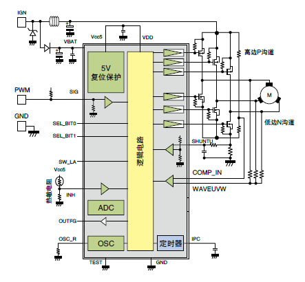
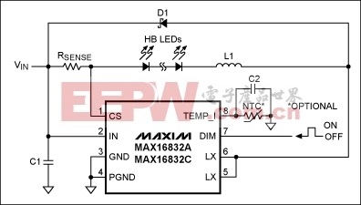
Board terminals (Figure 1)
- Inputs: VIN1, VIN2, input AC supply
- Outputs: LED+, LED-, output LED anode and cathode connections
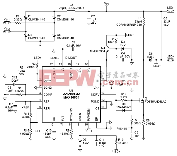
Figure 1. The schematic for the reference design.
Compatibility issues for electronic transformers and dimmers
Electronic transformers are a lower cost, smaller, and lighter alternative to traditional magnetic transformers for converting the 120VAC/230VAC line voltage to 12VAC and to supply an MR16 lamp. Electronic transformers modulate the input AC voltage with a frequency of 35kHz to 40kHz, and then feed this signal to a high-frequency transformer that converts 120/230VAC to 12VAC. Thanks to this high-frequency modulation, the transformer can be less expensive, smaller, and lighter. The 35kHz to 40kHz modulation is done with a self-oscillating circuit that uses a proportional base drive for the bipolar transistors that function as the switches for a half bridge.Electronic transformers are designed to have halogen lamps as loads, and not LED lamps. For the transformer to work properly, it needs a minimal amount of load current through the cycle of the line voltage. If the load current falls below this minimum, or if high load-current transients bring it below this minimum, the transformer turns off during the cycle of the line voltage. If this happens, the lamp light can flicker. With halogen lamps, there is no problem having enough load current, because they are purely resistive loads and the power exceeds 20W. Moreover, the electronic transformers are designed to operate with resistive loads, as are halogen lamps.
When electronic transformers are used with halogen or incandescent lamps, two issues must be solved.
- LED lamps are, in general, not purely resistive loads. In particular, if the driver is a simple voltage rectifier followed by a DC-DC converter, its input current is made of short, high spikes of current at each half cycle of the input voltage. This is not good for transformers;
- LED lamps are more efficient than halogen lamps. While this is certainly good, it can be an issue for compatibility with electronic transformers because the load current of LED lamps is, of course, lower.
Trailing-edge dimmers reduce the amount of lamp light by cutting the final part of the line voltage at each half cycle.
Sometimes the infrastructure still includes a magnetic transformer instead of an electronic one. A magnetic transformer has the same requirements for resistive behavior of the load and minimum load current as does an electronic transformer. However, if a dimmer is present (leading-edge dimmers are typically used with magnetic transformers), the dimmer requires a resistive load and a minimum load current. In short, the LED driver has similar constraints to those mentioned above for electronic transformers.
Description of the circuit
This circuit is a buck-boost converter, composed of inductor L1, switching MOSFET Q1, and power diode D6. It works in fixed-frequency, continuous-conduction mode.The solution presented here uses an active, power factor correction (PFC) approach to control and shape the input current so it is compatible with electronic transformers and dimmers. Active PFC provides the best control of the input current; it keeps the current above the minimum required by the dimmer and transformer for the largest part of the input voltage cycle and, thus, avoids transient spikes of that current. Active PFC is, therefore, the best approach to design a dimmable lamp with no flicker.
Active PFC does not require large value (i.e., electrolytic) input capacitors. This is an advantage of the design. In this solution the input capacitor (C2) is a small value and ceramic. This solution works without electrolytic capacitors, which considerably extends the lamp lifetime.
LEDs dissipate most of the power provided to them by conduction. Meanwhile, MR16 LED lamps have little space for heatsinks because of their small size. Consequently, they often run at high temperatures in the +80°C to +100°C range. At those temperatures, even the lifetime of high-grade electrolytic capacitors is limited to little more than 10,000 hours, which is too few hours for an LED lamp.
Active PFC in this solution shapes the input current as a square wave, as in Figure 2.
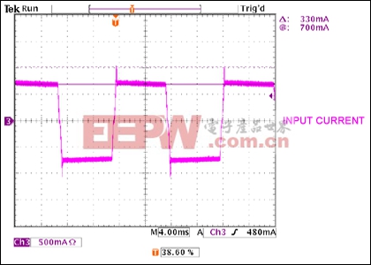
Figure 2. Input current for the LED driver.


评论