三相BLDC和PMSM设计的低压马达控制方案

3-Phase BLDC/PMSM Low- Voltage Motor Control Drive
The MC9S08AC16 Series devices are members of the low-cost, high-performance HCS08 Family of 8-bit microcontroller units (MCUs). All MCUs in the family use the enhanced HCS08 core and are available with a variety of modules, memory sizes, memory types, and package types.
MC9S08AC16 Series Devices
Consumer Industrial
― MC9S08AC16
MC9S08AC8
Automotive
― MC9S08AW16A
― MC9S08AW8A
8-Bit HCS08 Central Processor Unit (CPU)
40-MHz HCS08 CPU (central processor unit)
20-MHz internal bus frequency
HC08 instruction set with added BGND instruction
Background debugging system
Breakpoint capability to allow single breakpoint setting during in-circuit debugging (plus two more breakpoints in on-chip debug module)
Debug module containing two comparators and nine trigger modes. Eight deep FIFO for storing change-of-flow addresses and event-only data. Debug module supports both tag and force breakpoints.
Support for up to 32 interrupt/reset sources
Memory Options
Up to 16 KB of on-chip in-circuit programmable FLASH memory with block protection and security options
Up to 1 KB of on-chip RAM
Clock Source Options
Clock source options include crystal, resonator, external clock, or internally generated clock with precision NVM trimming
System Protection
Optional computer operating properly (COP) reset with option to run from independent internal clock source or bus clock
Low-voltage detection with reset or interrupt
Illegal opcode detection with reset
Illegal address detection with reset
Power-Saving Modes
Wait plus two stops
Peripherals
ADC ― 8-channel, 10-bit analog-to-digital converter with automatic compare function
SCI ― Two serial communications interface modules with optional 13-bit break
SPI ― Serial peripheral interface module
IIC ― Inter-integrated circuit bus module to operate at up to 100 kbps with maximum bus loading; capable of higher baud rates with reduced loading
Timers ― Three 16-bit timer/pulse-width modulator (TPM) modules ― Two 2-channel and one 4-channel; each has selectable input capture, output compare, and edge-aligned PWM capability on each channel. Each timer module may be configured for buffered,centered PWM (CPWM) on all channels
KBI ― 7-pin keyboard interrupt module
Input/Output
Up to 38 general-purpose input/output (I/O) pins
Software selectable pullups on ports when used as inputs
Software selectable slew rate control on ports when used as outputs
Software selectable drive strength on ports when used as outputs
Master reset pin and power-on reset (POR)
Internal pullup on RESET, IRQ, and BKGD/MS pins to reduce customer system cost
Package Options
48-pin quad flat no-lead package (QFN)
44-pin low-profile quad flat package (LQFP)
42-pin shrink dual-in-line package (SDIP)
32-pin low-profile quad flat package (LQFP)
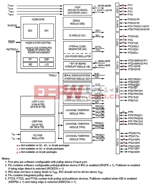
图1.MC9S08AC16系列方框图
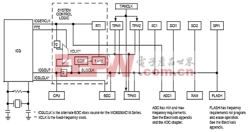
图2.MC9S08AC16系统时钟分布方框图
三相BLDC/PMSM低压马达控制驱动方案
Freescale’s 3-Phase BLDC/PMSM Low-Voltage Motor Control Drive is a 3-phase power stage that will operate with DC input voltages in the range 12C24 V, 4 A. Together with the daughter boards, it provides a software-development platform that allows algorithms to be written and tested without designing and building any hardware. It supports a variety of algorithms for PMSM and brushless DC (BLDC) motors.
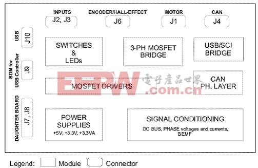
The 3-Phase BLDC/PMSM Low-Voltage Motor Control Drive contains reverse-polarity protection circuitry, MOSFET-gate-drive circuits, analog-signal conditioning, low-voltage power supplies and bridge MOSFETs. The power devices do not need to be mounted on a heatsink.
There are controller daughter boards available with these controllers:
MC56F8013/23 ― LQFP32
MC9S08AC16 ― LQFP44
MCF51AC256 ― LQFP80
MC9S08MP16 ― LQFP48
MC56F8006 ― LQFP32
板主要特性:
Power supply voltage input 12C24 V DC, extended up to 50 V (see chapter 2.2 Electrical Characteristics for details)
Output current 4 A
Power supply reverse polarity protection circuitry
3-phase bridge inverter (6 MOSFET’s)
3-phase MOSFET gate driver with overcurrent and undervoltage protection
3-phase and DC-bus-current-sensing shunts
DC-bus voltage sensing
3-phase back-EMF voltage-sensing circuitry
Low-voltage on-board power supplies
Encoder/hall sensor sensing circuitry
Motor power and signal connectors
2 connectors for daughter board connection
CAN physical layer
USB interface
User LED, power-on LED, 6 PWM LED diodes, and SCI activity LED diodes
Up, down, toggle switches
Reset push-button
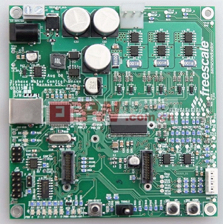
图3.三相BLDC/PMSM低压马达控制驱动板外形图


评论