文本LCD模块的控制FPGA

这是一个1行x 16个字符的模块:
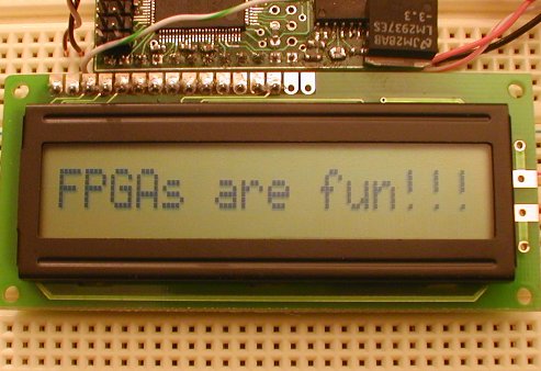
要控制LCD模块,您需要11个IO引脚来驱动8位数据总线和3个控制信号。3个控制信号是:
大多数LCD模块都基于HD44780芯片或是兼容的。查阅Wikipedia以获取更多信息。
7位设计
让我们用FPGA板驱动LCD模块。
这是我们设计的框图:
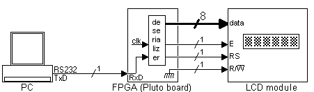
Pluto从PC串行端口接收数据,对其进行反序列化,然后将其发送到LCD模块。解串器与串行接口项目中的模块相同,因此此处仅对其进行实例化。
module LCDmodule(clk, RxD, LCD_RS, LCD_RW, LCD_E, LCD_DataBus);
input clk, RxD;
output LCD_RS, LCD_RW, LCD_E;
output [7:0] LCD_DataBus;
wire RxD_data_ready;
wire [7:0] RxD_data;
async_receiver deserializer(.clk(clk), .RxD(RxD), .RxD_data_ready(RxD_data_ready), .RxD_data(RxD_data));
每当串行端口提供一个字节时,“ RxDdataready”将在一个时钟周期内处于活动状态。
PC通过串口以8位模式向我们发送数据。理想情况下,我们需要从PC接收9位,以便我们可以驱动8位数据总线和LCD模块的“ RS”线。现在,让我们使用接收到的数据的MSB(第7位)来驱动“ RS”,并将仅7位发送到数据总线。
assign LCD_RS = RxD_data[7];
assign LCD_DataBus = {1'b0, RxD_data[6:0]};
// sends only 7 bits to the module, padded with a '0' in front to make 8 bits
assign LCD_RW = 0;
我们从不读取LCD模块,所以R / W线是接地的。
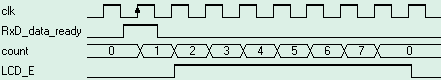
最后一个麻烦是“ E”信号需要长时间激活,即220ns。从FPGA的角度来看,这很长,因为我使用的是25MHz时钟(周期为40ns)。因此,“ E”至少需要驱动5.5个时钟。在这里,我们使用一个计数器对时钟进行计数,将其驱动7个时钟。
reg [2:0] count;
always @(posedge clk) if(RxD_data_ready | (count!=0)) count <= count + 1;
“ E”信号是通过寄存器创建的,因此可以保证无干扰。
reg LCD_E;
always @(posedge clk) LCD_E <= (count!=0);
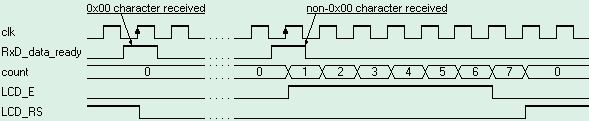
波形如下所示:
HDL设计在这里。
软件方面
我们对LCD进行初始化并发送一些要显示的数据。
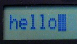
以下是初始化LCD模块并显示“ hello”的C代码。
void main(){
  OpenComm();   // initialize the LCD module
  WriteCommByte(0x38);   // "Function Set" in 8 bits mode
  WriteCommByte(0x0F);   // "Display ON" with cursors ON
  WriteCommByte(0x01);   // "Clear Display", can take up to 1.64ms, so the delay
  Sleep(2);   // display "hello"
  WriteCommByte('h' + 0x80);
  WriteCommByte('e' + 0x80);
  WriteCommByte('l' + 0x80);
  WriteCommByte('l' + 0x80);
  WriteCommByte('o' + 0x80);
  CloseComm();
  }
完整的代码在这里。
要获取有关HD44780指令集的更多信息,请在此处检查。
8位设计
主要缺点是较早的设计是我们仅向LCD数据总线发送7位。这是一个问题,因为无法再使用LCD模块的设置DD RAM地址命令。
一种简单的解决方法是使用转义符。我们选择了字符0x00。
新协议如下:
新的C代码是:
void main(){
  OpenComm();   // initialize the LCD module
  WriteCommByte(0x00);  WriteCommByte(0x38);   // "Function Set" in 8 bits mode
  WriteCommByte(0x00);  WriteCommByte(0x0F);   // "Display ON" with cursors ON
  WriteCommByte(0x00);  WriteCommByte(0x01);   // "Clear Display", can take up to 1.64ms, so the delay
  Sleep(2);
  WriteCommByte('h');
  WriteCommByte('e');
  WriteCommByte('l');
  WriteCommByte('l');
  WriteCommByte('o');
  WriteCommByte(0x00);  WriteCommByte(0xC0);   // go on second half of LCD
  WriteCommByte('e');
  WriteCommByte('v');
  WriteCommByte('e');
  WriteCommByte('r');
  WriteCommByte('y');
  WriteCommByte('o');
  WriteCommByte('n');
  WriteCommByte('e');
  CloseComm();
  }
新的HDL代码如下所示:
module LCDmodule(clk, RxD, LCD_RS, LCD_RW, LCD_E, LCD_DataBus);
input clk, RxD;output LCD_RS, LCD_RW, LCD_E;
output [7:0] LCD_DataBus;
wire RxD_data_ready;
wire [7:0] RxD_data;
async_receiver deserialer(.clk(clk), .RxD(RxD), .RxD_data_ready(RxD_data_ready), .RxD_data(RxD_data));
assign LCD_RW = 0;assign LCD_DataBus = RxD_data;
wire Received_Escape = RxD_data_ready & (RxD_data==0);
wire Received_Data = RxD_data_ready & (RxD_data!=0); reg [2:0] count;
always @(posedge clk) if(Received_Data | (count!=0)) count <= count + 1;
// activate LCD_E for 6 clocks, so at 25MHz, that's 6x40ns=240ns
reg LCD_E;
always @(posedge clk)if(LCD_E==0)
  LCD_E <= Received_Data;
  else
  LCD_E <= (count!=6);
  reg LCD_instruction;
  always @(posedge clk)if(LCD_instruction==0)
  LCD_instruction <= Received_Escape;
  else
  LCD_instruction <= (count!=7);
  assign LCD_RS = ~LCD_instruction;
  endmodule
HD44780规范显示,“ E”变低后,“ RS”必须在10ns内有效。因此,您会注意到这里“ E”仅被驱动6个时钟,并且“ LCDinstruction”标志仅在时钟7之后被复位,以提供25ns的空间。
That's all folks!轮到您尝试了。


评论