使用基于模型设计开发世界上最先进的假肢

很少有人知道当手臂拿起一个球时神经、臂膀和传感系统之间的交互。为了模拟这一自然反应过程,可以通过微处理器、嵌入式控制软件、执行机构和传感器来构造这一系统从而来研究它们之间的复杂关系。这也是美国国防高级研究计划署(DARPA)革命性假肢计划所面临的挑战。
美国约翰霍普金斯大学应用物理实验室是领导性的全球团队,包括政府机构、大学、私有企业,他们的任务是开发世界上最先进的假肢,此假肢由神经输入控制,使佩戴者感觉是一个真的手臂一样能够以一定的速度、灵敏度和力去运动。先进的传感反馈技术能够感知物理输入,如压力、力和温度。
这个项目中具有里程碑意义的关键部分是虚拟综合环境的开发,一个完整的手臂系统的仿真环境使用The Mathworks工具和基于模型设计。虚拟综合环境具有标准化的架构和定义完善的界面,能够使二十多不同领域专家很好地合作。
The Mathworks工具基于模型设计也被用在其他开发阶段,包括对臂的机械系统进行建模、测试新的神经解码算法和开发与验证控制算法。
为 DARPA计划开发的两个原型手臂使用了目标肌肉神经系统,这项技术是由芝加哥康复研究院Todd Kuiken博士研发的,内容包括从被切除手臂到未使用的伤害处的肌肉区域的残留神经的传输。在临床评估中,第一个原型能够使患者完成各种功能任务,包括从口袋里拿一个信用卡。
Virtual Integration Environment Architecture
The VIE architecture consists of five main modules: Input, Signal Analysis, Controls, Plant, and Presentation.
The Input module comprises all the input devices that patients can use to signal their intent, including surface electromyograms (EMGs), cortical and peripheral nerve implants, implantable myoelectric sensors (IMESs) and more conventional digital and analog inputs for switches, joysticks, and other control sources used by clinicians. The Signal Analysis module performs signal processing and filtering. More important, this module applies pattern recognition algorithms that interpret raw input signals to extract the user’s intent and communicate that intent to the Controls module. In the Controls module, those commands are mapped to motor signals that control the individual motors that actuate the limb, hand, and fingers.
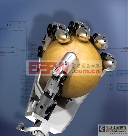
The Plant module consists of a physical model of the limb’s mechanics. The Presentation module produces a three-dimensional (3D) rendering of the arm’s movement (Figure 1).
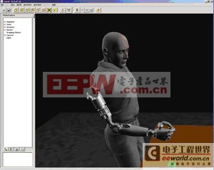
图1 假肢三维视图
Interfacing with the Nervous System
Simulink? and the VIE were essential to developing an interface to the nervous system that allows natural and intuitive control of the prosthetic limb system. Researchers record data from neural device implants while the subjects perform tasks such as reaching for a ball in the virtual environment. The VIE modular input systems receive this data, and MATLAB? algorithms decode the subject’s intent by using pattern recognition to correlate neural activity with the subject’s movement (Figure 2). The results are integrated back into the VIE, where experiments can be run in real time.
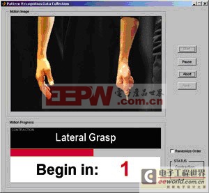
图2 纽布朗斯威克大学开发了MATLAB应用程序,记录用于模式识别的运动数据。
The same workflow has been used to develop input devices of all kinds, some of which are already being tested by prosthetic limb users at the Rehabilitation Institute of Chicago.
Building Real-Time Prototype Controllers
The Signal Analysis and Controls modules of the VIE form the heart of the control system that will ultimately be deployed in the prosthetic arm. At APL, we developed the software for these modules. Individual algorithms were developed in MATLAB using the Embedded MATLAB? subset and then integrated into a Simulink model of the system as function blocks. To create a real-time prototype of the control system, we generated code for the complete system, including the Simulink and Embedded MATLAB components, with Real-Time Workshop?, and deployed this code to xPC Target?.
This approach brought many advantages. Using Model-Based Design and Simulink, we modeled the complete system and simulated it to optimize and verify the design. We were able to rapidly build and test a virtual prototype system before committing to a specific hardware platform. With Real-Time Workshop Embedded Coder? we generated target-specific code for our processor. Because the code is generated from a Simulink system model that has been safety-tested and verified through simulation, there is no hand-coding step that could introduce errors or unplanned behaviors. As a result, we have a high degree of confidence that the Modular Prosthetic Limb will perform as intended and designed.
Physical Modeling and Visualization
To perform closed-loop simulations of our control system, we developed a plant model representing the inertial properties of the limb system. We began with CAD assemblies of limb components designed in SolidWorks? by our partners. We used the CAD assemblies to automatically generate a SimMechanics? model of the limb linked to our control system in Simulink.
Finally, we linked the plant model to a Java? 3D rendering engine developed at the University of Southern California to show a virtual limb moving in a simulated environment.
更多医疗电子信息请关注:21ic医疗电子频道


评论