用标准三端复位管理器实现手动复位功能

简单的增加一对电阻、一个电容、一个按键开关转换标准三端复位管理器为手动复位
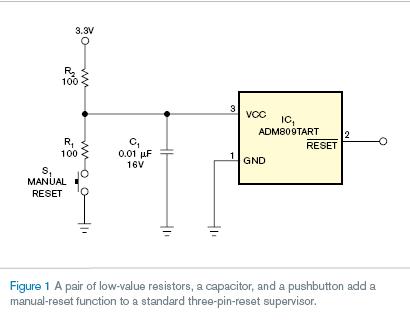
本文引用地址:https://www.eepw.com.cn/article/78178.htm增加手动复位功能通常需要手动复位输入的新电路。但是通过增加一对低值电阻,标准三端复位管理器能够实现普遍应用。电路如图1所示,从按下手动复位按钮时刻起,确保纯净的复位信号。当复位按钮被触发,VCC电压降到复位管理器最小复位限(S1按下时,VCC电压为R1/R2的电压分压)。这个动作导致复位管理器复位输出有效。松开S1,VCC电压恢复到高于最大复位限,其中复位一直有效到复位管理器完成time-out时间段。
S1不被按下时,复位管理器供电电流和复位输出装填会导致R2电压降的情况。对绝大多数复位管理器,最大供电电流为50 µA。对绝大多数设计,复位输出经过一或两个CMOS输入,每个输入需要10 µA。带两个CMOS的设备接到复位,经过R2的总电流将为(2×10 µA)+50 µA=70 µA。经过R2的电压降为复位管理器复位限电压加上70 µA×100Ω=7 mV的电压和。
考虑替换方式来选择R1, R2和C1的值。旁路电容C1的值应该足够低 到允许复位管理器检测瞬时电压的下降。R2 和C1的值决定时间常数,例如时间常数为100Ω×0.01 µF=1 µsec。这个公式显然比可调电源的衰减率更高。
S1触发时,电流流过R1 和R2。在图1的电路中,S1触发时电流为3.3V/(100Ω+100Ω)=16.5 mA。电流大小满足线性功率系统,但是不适合电池供电系统。通过增大R1值的方法减小电流,确保复位管理器VCC低于最小复位限。也可以增大R2,但是会导致电压降增加和瞬时响应减缓。提醒注意的是,增加手动复位电流只在手动复位有效时发生,典型的系统电流下降在有效时复位才会出现。
附英文原文
Add a manual reset to a standard three-pin-reset supervisor
Simply adding a couple of resistors, a capacitor, and a pushbutton switch transforms a standard three-pin-reset supervisor into a manual reset.
Derek Vanditmars, Delta Controls, Surrey, BC, Canada; Edited by Charles H Small and Brad Thompson -- EDN, 4/12/2007
Adding a manual reset to a design usually involves designing in a new part with a manual-reset input. But, by adding a couple of low-value resistors, a standard three-pin-reset supervisor can work in most applications. The circuit in Figure 1 ensures a clean signal during and after you have pressed the manual-reset button. When you activate the manual-reset button, the supply voltage drops below the reset supervisor’s minimum reset threshold because of the R1/R2 voltage divider formed when S1 is active. This action causes the reset supervisor to activate its output. When you release S1, the supply voltage returns to above the reset-supervisor maximum-reset threshold, and remains active for the time-out period of the reset supervisor.
When you do not press S1, R2 has a voltage drop arising from the reset supervisor’s supply current and output loading. For most reset supervisors, the maximum supply current is 50 µA. For most designs, the output goes to one or more CMOS inputs that require about 10 µA each. With two CMOS devices connected to , the total current through R2 would be (2×10 µA)+50 µA=70 µA. The voltage drop across R2 due to the current flow effectively adds 70 µA×100Ω=7 mV to the reset supervisor’s reset-threshold voltage.
You should consider several trade-offs for the
selection of values for R1, R2, and C1. The value of the local bypass capacitor, C1, for the reset supervisor should be low enough to allow the reset supervisor to detect transient supply-voltage drops. The time constant of R2 and C1 determines this factor; in this example, the time constant is 100Ω×0.01 µF=1 µsec. This figure is typically much higher than the decay rate of a regulated power supply that has lost power.
When you activate S1, current flows through R1 and R2. In the circuit in Figure 1, the current flow when you activate S1 is 3.3V/(100Ω+100Ω)=16.5 mA. This amount of current would be OK for a line-powered system but may not be OK for a battery-powered system. You can reduce the current by increasing the value of R1 and ensuring that the reset supervisor’s supply voltage drops below the minimum reset threshold. You can also increase the value of R2, along with that of R1, but doing so will cause increased voltage drop and slower response to transients. Note that the increased current of the manual reset occurs only while the manual reset is active, and typical system current drops while is active.
英文原文地址:http://www.edn.com/article/CA6430341.html?industryid=47041
电容相关文章:电容原理 电容传感器相关文章:电容传感器原理
评论