模拟集成电路的低电压系统-Analog ICs for Lo

Some applications, monitoring a power supply's output voltage for instance, require ultra-low power consumption. The MAX9017A, which operates from a 1.8V to 5.5V supply, draws only 1.2µA (typ) of supply current, and integrates a voltage reference and a comparator within a single package.
Microprocessor Supervisory Circuits
All microprocessor (µP) systems require some form of "supervision" to guard against erratic operation. The supervisor can be as simple as a reset generator, which ensures known startup conditions by issuing a system reset following the application of power. But many supervisors include other functions as well, such as backup-battery management, memory-write protection, and "watchdog" timers for monitoring software execution.Backup batteries, for example, ensure an uninterrupted flow of power to critical circuits (like the CMOS memory and the real-time clock) when VCC is absent. By monitoring VCC, the µP supervisor decides when to switch the system over to the backup battery. Low-voltage operation, however, presents an engineering problem that doesn't exist in 5V systems.
Five-volt systems simply compare VCC with the backup voltage and switch to backup whenever VCC is lower. But, this approach can cause false switchovers in a lower voltage system: lithium backup batteries measure as high as 3.6V when fresh, which is higher than the 3.0V limit for VCC in a 3.3V system. Maxim's supervisors avoid this problem by allowing the backup voltage to exceed VCC, and initiating a switchover only when VCC falls below a selected threshold.
The MAX823/MAX824 offers a voltage monitor and a watchdog timer in 5-pin SC70 and SOT23 packages (Figure 7).
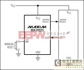
Figure 7. The MAX823 offers a supply voltage monitor, a watchdog, and a manual reset all in a single 5-pin SC70/SOT23 package.
The MAX806R/S/T include battery switchover circuitry and monitor both the 3V and 5V VCC voltages in a dual-voltage system (Figure 8). In this circuit, the main VCC comparator monitors the 3V supply, and the power-fail (PFI) comparator monitors the 5V supply.
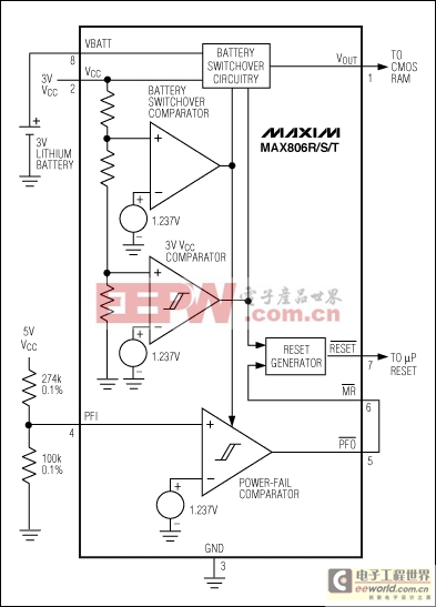
Figure 8. Configured as shown, this µP supervisor monitors 5V and 3V VCC in a dual-voltage system.
Internal circuitry issues a reset when the 3V VCC goes out of tolerance. The 5V VCC's trip threshold (4.527V to 4.726V) is set by 0.1% resistors; when 5V falls out of tolerance, the power-fail comparator output (PFO) pulls down the manual-reset input (MR). Thus, an out-of-tolerance condition for either VCC causes the chip to issue a reset.
Some of Maxim's low-voltage supervisors protect the memory ICs with chip-enable (CE) gating. CE gating enables the supervisor to protect the memory by blocking read and write operations during power faults. The MAX792 and MAX820, for example, feature CE gating with a propagation delay through the supervisor of only 10ns. (Short delays allow slower, cheaper memories because the CE delay takes less of the memory cycle time.) These devices also offer manual reset, power-on reset, power-fail warning, and watchdog timing.
The low-power MAX6741 monitors two system voltages, and requires only 6µA of supply current (Figure 9). All members of this supervisor family are available with either push-pull or open-drain outputs, come in the tiny SC70 package, and can monitor voltages down to 0.488V.
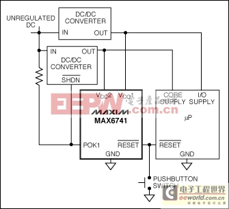
Figure 9. The MAX6741 monitors two voltages and generates a reset signal if either drop out of tolerance.
Voltage References
A three-terminal bandgap reference is the best choice when a precision, low-voltage reference with minimal supply current is specified. Three-terminal references generally offer lower operating currents than do the two-terminal zener diodes types (Figure 10).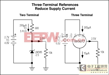
Figure 10. A three-terminal voltage reference, unlike a two-terminal type, draws constant supply current as the input voltage varies.
Output voltage should be as high as possible for maximum SNR, and the input-to-output voltage difference should be low. A 2.5V reference powered from 3V ±10%, for example, must operate with headroom as low as 200mV. The MAX6029 precision 2.5V reference meets this stringent requirement. It accepts inputs as high as 12V, and draws only 5µA of supply current.
The MAX6029 can source 4mA, and sink 1mA, with a corresponding guaranteed load regulation of 0.7µV/µA (source) and 5.5µV/µA (sink). Temperature drift is 30ppm/°C, and line regulation is typically 27µV/V over the 2.5V to 12.6V input range.
Analog Switches
Low-voltage analog switches with guaranteed precision have improved dramatically in recent years. The MAX4651/MAX4652/MAX4653 quad, 4Ω, single-pole/single-throw (SPST) analog switches operate from a single 1.8V to 5.5V supply. As expected, lower voltage operation yields somewhat higher on-resistance and moderately lower switching speeds than are available with higher-voltage supplies (Figure 11).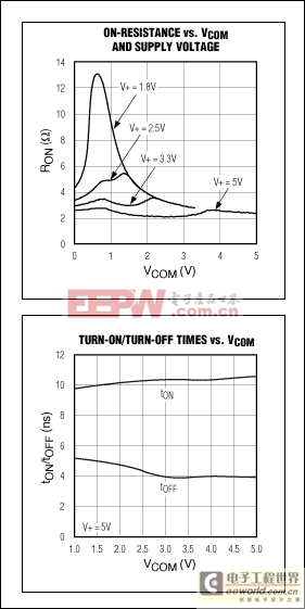
Figure 11. On-resistance and switching times for the MAX4653 analog switch.
Interface Transceivers
USB
The universal serial bus (USB) is very common on computers and peripherals, and while the bus operates at 5V, many signals that need to interface with the bus operate at lower voltages. Maxim makes devices that interface between the low-voltage logic and the USB voltage level, and handle the various USB-interface-specific control signals. The MAX3453 interfaces USB 1.1/2.0 to logic levels from 1.65V to 3.6V, and accepts a power supply as low as 3.1V, which is ideal for lithium battery-powered logic signals. Figure 12 shows a typical circuit connecting low-voltage logic to a USB using the MAX3453.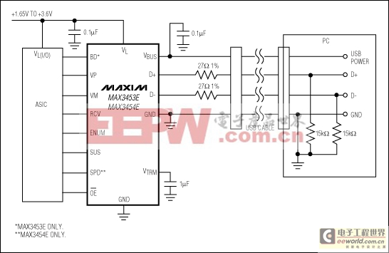
Figure 12. The MAX3453 USB transceiver connects low-voltage logic with the 5V USB bus, and is fully USB 1.1/2.0 compliant at 12Mbps and 1.5Mbps.
RS-232 and RS-485
RS-232, also known as 232E (officially EIA/TIA-232-E), appeared in the days of mainframe and mini computers, at a time when ±12V power supplies were common, and the original RS-232 transceivers required ±12V for operation. Voltage drops reduced the output swing to about ±9V, so the required minimum was set still lower, at ±5V.The advent of portable and low-voltage equipment has spawned a new serial-interface specification to replace the old 232E standard, EIA/TIA-562 (562 for brevity). This new standard became effective in 1991. The 562 and 232E standards are electrically compatible, so the new 562 designs will mate with existing 232E equipment and vice versa. Despite the new standard, the term RS-232 lingers, and has come to mean both or either standard in loose parlance.
A comparison of certain 232E and 562 specifications is presented in Table 4. Note that the driver output swings differ (±5V vs. ±3.7V), but the receiver input thresholds are the same (±3V). The 562 devices' ±3.7V minimum output swings allow them to communicate with 2

DIY机械键盘相关社区:机械键盘DIY


评论