监测集成电路监控电池供电设备
To ensure correct operation, most microprocessor-based systems require supervision during power-up and power-down, and when entering or exiting shutdown or sleep mode. The supervisor may only provide a power-on reset, or it may offer additional functions, such as backup-battery management, memory-write protection, low-line early warning, or a software watchdog (Figure 1).
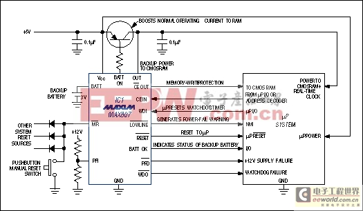
Figure 1. A feature-laden µP supervisor (IC1), with the help of the µP itself, performs a variety of functions in this typical application circuit.
You can get these functions all together or in various combinations, by selecting one of the many available microprocessor (µP) supervisor ICs (also called power-on resets, power-good circuits, reset circuits, etc.). The following discussion helps you choose the one best suited to your application, and offers solutions for many common µP supervisory problems.
First, determine the VCC threshold voltage for which resets will be issued. (The assertion of RESET blocks µP operation when the supply voltage is out of tolerance.) Typical power-on reset circuits consist of a voltage reference, comparator, and timer. Comparing the reference voltage with the rising VCC (via a voltage divider) enables the comparator to make an output transition when VCC crosses a threshold (VRST) set by the divider. This transition triggers the timer, which maintains the reset as necessary to prevent software execution until the system oscillator has started and stabilized.
When VCC falls below VRST, the supervisor again issues a reset and maintains it as long as VCC remains below VRST. For some microcontrollers (µCs), a simple RC circuit is recommended for timing this power-on reset; others provide reset circuitry on the µC chip. Those approaches, however, assume the supply-voltage behavior is predictable. They don't protect against the code-execution errors that can occur as a result of power-down, or more importantly, during "brownouts," in which VCC can fall slightly out of regulation for an extended period. Supervisory ICs are most valuable for these power-down and brownout conditions.
Factors that affect the threshold value include the tolerance on VCC, the minimum and maximum supply voltages allowed for the system ICs, and the possible need to specify the design for worst-case combinations of these variables. For many systems, the reset function is not intended to cover all possible conditions including the worst-case combinations over temperature. A system might include ICs specified only to 4.75V minimum, for example, yet depend on a supervisor whose min/max trip threshold is 4.5V/4.75V. In that case, the supervisor asserts a reset only after VCC has fallen below the minimum voltage guaranteed for IC operation.
The alternative is to choose a reset threshold between 4.75V and (perhaps) 4.85V. However, these values might allow resets to occur before they are needed. In general, you must decide whether you can tolerate a lower threshold, in order to gain operating time at lower voltages; or whether the extra expense and reduced operating time associated with a higher threshold are a fair trade for the benefit of tighter accuracy. Supervisor ICs are now available with reset-threshold tolerances as tight as ±1% (Figure 2).
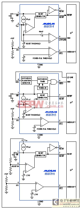
Figure 2. These three ICs offer different combinations of supervisory functions, but each monitors VCC with ±1% accuracy.
Monitor More than One Supply
Many applications require both 5V and 3.3V supplies, and if either loses regulation, you must typically reset the whole system. You also need an appropriate duration of power-on reset to ensure proper operation during power-up. A supervisory IC with a power-fail comparator and a manual reset input (active-low MR) offers a cost-effective solution to these problems.If you choose a supervisory IC whose internal threshold is set to monitor 3.3V, you can then use the uncommitted power-fail comparator to monitor the 5V supply: simply route the power-fail-comparator output (PFO) back to the active-low MR input (Figure 3). These connections cause the IC to assert active-low RESET when either supply loses regulation. The IC is powered from 3.3V, so the active-low RESET output swings 3.3V when active. That level satisfies the VIH requirement of most 5V processors, so the active-low RESET output can usually drive both 3V and 5V processors. If necessary, you can route other system-reset signals to the active-low MR input with diode-OR connections. (Even without these connections a diode is required from the active-low MR input to the PFO output.)
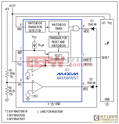
Figure 3. Configured as shown, this supervisory IC monitors both 3.3V and 5V supplies.
Early Warning for Shutdown Routine
Critical systems often require an early warning when the power-supply voltage (VCC) begins to fall. The warning allows time for the µP to store vital data and perform "housekeeping" chores before the declining VCC causes the supervisor to issue a hard reset. If the raw dc input voltage is accessible, it can be monitored with an undervoltage or power-fail comparator, which in turn asserts a processor interrupt to indicate when the unregulated supply is collapsing.If you don't have access to this raw input voltage, you must generate the early-warning and reset signals while monitoring the same regulated supply. You can use a single threshold detector for the low-line signal plus a delay timer for the reset signal, or use two different comparators—one for tLOWLINE and one for tRST. Either way, you must ensure that VCC remains valid long enough to complete the shutdown routine that follows an interrupt from the low-line signal.
The time required to complete a shutdown/backup routine varies widely with the application, as does the fall rate of VCC. Thus, you must adjust the delay from low-line to reset according to the application. The two-threshold approach is more flexible than the time-delayed-reset approach. By adjusting the low-line threshold tens of millivolts above the reset threshold and adjusting the VCC fall rate to comply with time requirements for the shutdown routine, you can make one IC serve many different applications.
In most battery-operated portable systems, reserve energy in the battery provides ample time to complete the shutdown routine during the interval between the low-line warning and reset. If the VCC fall time is rapid, as when a high-side switch is opened during normal operation, add capacitance on the load side of the switch to slow the decline of VCC and provide time for executing the shutdown routine. In MAX814 supervisors, for example, the power-fail comparator's delay (less than 50µs) may or may not affect your application.
First, calculate the worst-case time required for the shutdown routine. Using this value, the worst-case load current, and the minimum low-line to reset-threshold difference (VLR(min)), calculate the capacitance necessary for completion of the shutdown routine before reset occurs:
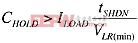
where ILOAD is the current being drained from the capacitor, VLR(min) is the minimum difference between the low-line and reset thresholds, and tSHDN is the time required for an orderly shutdown to occur, including the reset comparator's propagation delay.
Placing the low-line thresh


评论