太阳能邮箱项目电路,Solar Mailbox projec

太阳能邮箱项目电路,Solar Mailbox project
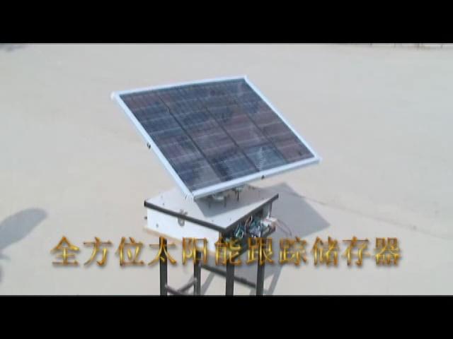
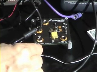
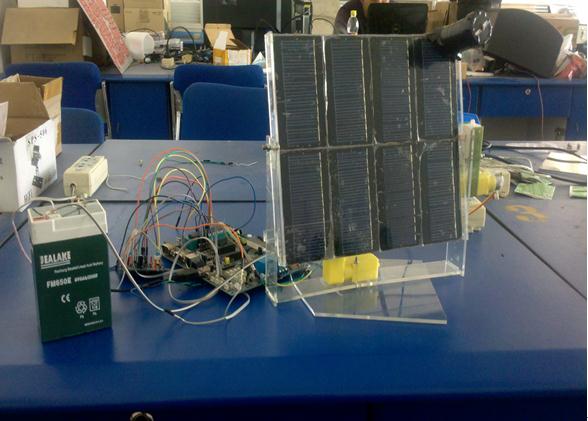
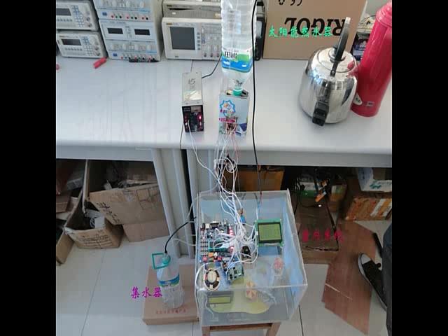
Final external Realization
The purpose of this project is to develop a self sufficient Mailbox (real one) that will be powered only by the sun and that will display the number of the house, but only in accordance with the battery level. The system must work autonomously when there is or not enough light to charge the battery.
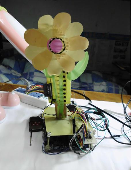
At night: Central Digit On, other one in PWM Modes
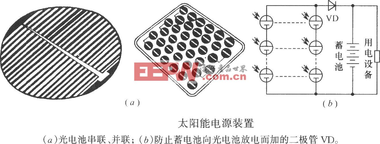
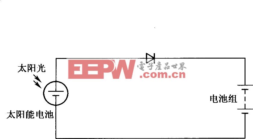
The Mailbox is powered by a 5V/80mA Polysilicon solar cell. The sun energy is used to charge a 3 AA NiMH battery.
At night, when there is no light, the PIC is driving the 3 Digit according with a sequence which is defined in its program given in Annex.
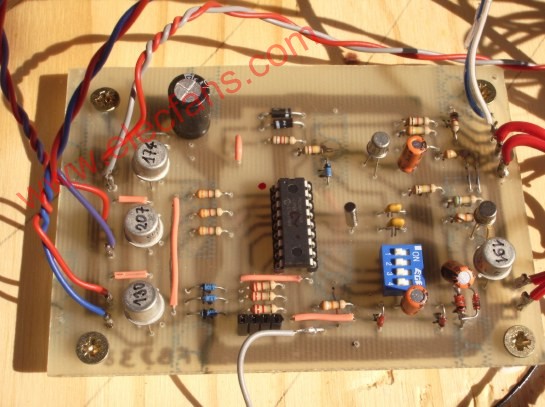
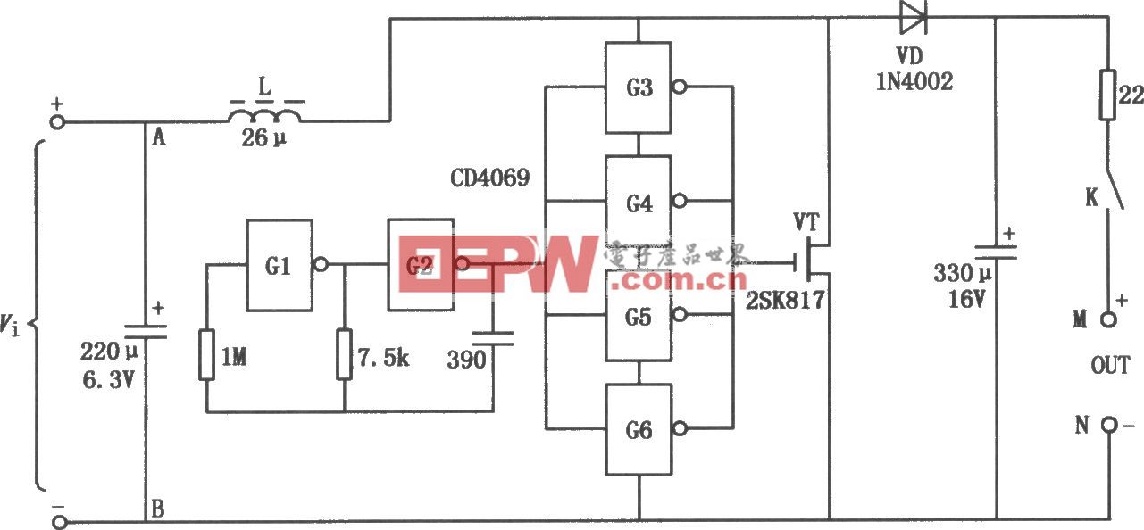
Schematic Explanation
click on image to download full resolution schematic
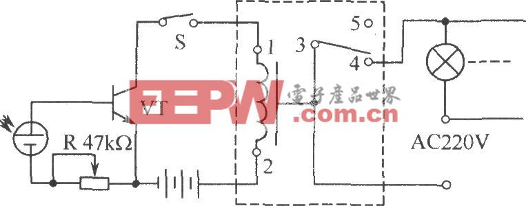
Charger_Control: The Solar Cell is charging the 3 AA NiMH cell trough the “Sziklai pair” composed by the T5 (2N2907) and T4 (1N1711). This is necessary to ensure a very low reverse current when the sun is off and the battery at full charge. Control of the charge can be applied on D5 with a "1" level from the PIC , which will reverse the T6 that define the current in T5 base. For Battery protection purpose, the value of Zener diode DZ6 must be 4.6V to prevent the battery for over-charging which will degrade significantly its life time. This function is not yet managed by the PIC program and is reserved for further use.
LED_OR_control: The 3 digits are controlled by 3 separate 2N1711 (each digit is compose about 20 white LED). The control signal is the OR between a PWM signal, that ensure a constant background level of light plus a "blinking" part which is the sequence generated by the PIC.
Sun_Sense: Just a low pas filter composed of R8 and C6. Beware that leakage current from the PIC can affect the level. This prevent R8 to be bellow 39KOhms.
Vbat_sense: These 2 diodes in serial create a 1.3V constant voltage that can be measured by the PIC to determine the level of the battery. This function is not yet managed by the PIC program and is reserved for further use.
Cpu: The PIC16F628 operates with a 32.768KHz crystal oscillator. This frequency have been selected, not to consume too much. In this condition, the PIC is able to operate down to 3V.
Behavioral Explanations
Apart when the Battery is totally low, the PIC is running and infinity loop which period is approximately 1 second, the red led is blinking accordingly.
During day light the SunSense signal is high and the PIC is not performing any operation (than the 1 second blinking loop). The Green led is on. If the battery voltage is low enough, the Solar cell is charging it. If the Battery voltage is above 4.6V (3 times 1.3V), then the DZ6 is drawing the current to ground protecting the battery cells. In the future Vbat_sense and Stop_Charge should be used.
During night the SunSense signal get low and the PIC is programmed t
- Generate a PWM signal (100Hz, Duty Cycle of 5%) on the PWM pin
- Generate a "blinking" sequence on the 3 separate control signals (1 minute period)
PIC Source code


评论