Battery Backup with Delay(具有时滞的备用电池)
 加入技术交流群
Battery Backup with Delay(具有时滞的备用电池)
Abstract: This application note explains that the simplest link from a main supply and backup battery to a load is the diode-OR connection. However simple that concept, a diode-OR does not work when the battery voltage exceeds the main supply voltage. The article presents a circuit which handles that condition. The MAX931 comparator with 2% reference is featured in the design.
This design idea appeared in the May 25, 2006 issue of Electronic Design magazine.
The simplest link from a main supply and backup battery to a load is the diode-OR connection. However, a diode-OR does not work when the battery voltage exceeds the main supply voltage. The Figure 1 circuit handles that condition. The main switch-mode supply voltage ranges from 7V to 30V, and the backup supply is a 9V battery.
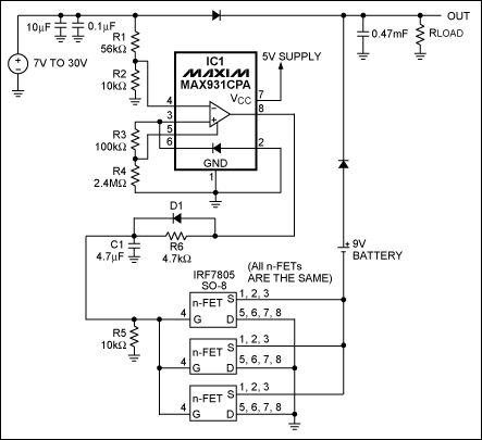
Figure 1. IC1, the MAX931 comparator, monitors the main supply voltage. It also turns on the backup battery by grounding its negative terminal when the main supply drops below 7.4V.
The MAX931 is an ultra-low-power comparator with a 1.182V bandgap reference. During normal operation the comparator output is low, the three parallel-connected n-channel FETs are off, and the battery's negative terminal floats. Power flows from the main supply to the load. When the main voltage declines to 7.4V the comparator's output goes high, turning on the n-FETs and grounding the negative terminal of the battery. Power then flows from the battery to the load (Figure 2).
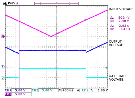
Figure 2. In response to a gradual decrease in the main supply voltage (channel 3 in Figure 1), the n-FET gate voltage goes high (channel 2). This activates the battery and drives the output voltage (channel 1) to 9V. As the main supply voltages passes 8.4V the n-FETs turn off, allowing the output to resume tracking the main supply voltage.
D1, C1, and R6 introduce a delay in the gate drive. This delay eliminates a supply-rail glitch that would otherwise occur when switching from the battery to the main supply. While those glitches can cause an unacceptable reset in the system's microcontroller, Figure 3 illustrates the absence of that effect with this circuit. Note that R3 and R4 set the hysteresis in the MAX931 to 800mV, as required for proper operation. See the MAX931 data sheet for calculation of those resistor values.
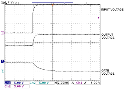
Figure 3. The output in Figure 1 responds without glitches in response to a fast restoration of the main supply voltage.
专栏文章内容及配图由作者撰写发布,仅供工程师学习之用,如有侵权或者其他违规问题,请联系本站处理。 联系我们
相关推荐
如何编写 Linux 设备驱动程序
555构成的机电一体化自行车防盗报警锁
MSP430 学习套件(七)
如何快速解决传导型EMI问题?
汽车MCU排名TOP10,最新出炉
555构成的“空城计”防盗报警器
MSP430 学习套件(六)
人形机器人产业链企业解读之 “人形机器人关节之心缔造者 -- 绿的谐波 “
关税博弈下,这些芯片或将涨价
MSP430 学习套件(八)
80C196的软件仿真问题?
深入理解Linux虚拟内存管理原书光盘1
三星已组建专注于1nm芯片开发的团队 量产目标定于2029年
请各位前辈们提供几种方案。
MSP430 学习套件(四)
密码门铃报警器(RS7255、KD9561)
单片视频编解码芯片
漏血报警器(555、μA741)
从元器件到测试系统:Pickering品英集团55年为用户构建自动测试全生命周期降本增效生态
万禾嵌入式Linux系统开发套件WH5307SDK简介
美国银行:若苹果iPhone迁回美国生产 成本将飙升超90%
为系统处理器编写Linux设备驱动程序
PIC仿真器及编程器
MSP430 学习套件(五)
图形化编程工具BetterState描述文件
寻仿真器
苹果要求供应商空运设备到美国:因零部件库存有限 供应链压力山大
美国放弃英伟达H20芯片出口限制:黄仁勋没办法高兴 或遭中国限购
探索射频放大器线性化的模拟预失真基本概念
555组成实用降温报警器