PIC单片机 配置位如何写 (MPLAB X集成开发环境,XC编译器)

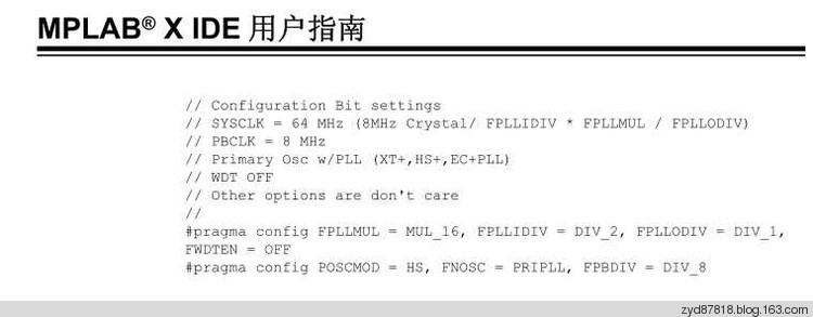
1:MPALB X IDE用户指南里面例子的配置位写法:
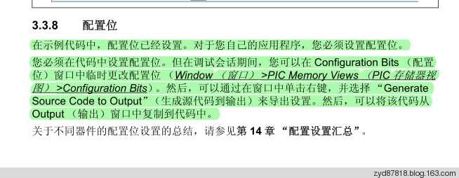
2:根据MPALB X IDE用户指南里面的描述,可以自动生成配置位的代码
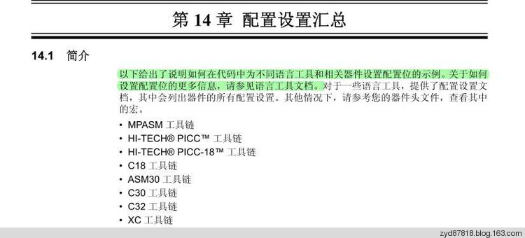
3:根据MPALB X IDE用户指南,说明配置位的编写是和编译器相关的,因此我们看编译器的说明文档
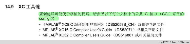
4:根据X8编译器的说明文档,看编译器安装目录下的文档说明
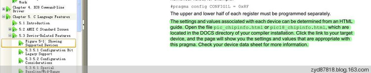
5:下面就是编译器安装目录下的文档说明
16F877A Support Information
#pragma config Usage
#pragma config =
For example:// Brown-out Reset Enable bit: BOR disabled
// Data EEPROM Memory Code Protection bit: Data EEPROM code protection off
// In-Circuit Debugger Mode bit: In-Circuit Debugger disabled, RB6 and RB7 are general purpose I/O pins
// Flash Program Memory Write Enable bits: Write protection off; all program memory may be written to by EECON control
// Oscillator Selection bits: XT oscillator
// Watchdog Timer Enable bit: WDT disabled
// Flash Program Memory Code Protection bit: Code protection off
// Low-Voltage (Single-Supply) In-Circuit Serial Programming Enable bit: RB3 is digital I/O, HV on MCLR must be used for programming
// Power-up Timer Enable bit: PWRT disabled
#pragma config BOREN = OFF, CPD = OFF, DEBUG = OFF, WRT = OFF, FOSC = XT, WDTE = OFF, CP = OFF, LVP = OFF, PWRTE = OFF
#pragma config =
For example:// Brown-out Reset Enable bit: BOR disabled
// Data EEPROM Memory Code Protection bit: Data EEPROM code protection off
// In-Circuit Debugger Mode bit: In-Circuit Debugger disabled, RB6 and RB7 are general purpose I/O pins
// Flash Program Memory Write Enable bits: Write protection off; all program memory may be written to by EECON control
// Oscillator Selection bits: XT oscillator
// Watchdog Timer Enable bit: WDT disabled
// Flash Program Memory Code Protection bit: Code protection off
// Low-Voltage (Single-Supply) In-Circuit Serial Programming Enable bit: RB3 is digital I/O, HV on MCLR must be used for programming
// Power-up Timer Enable bit: PWRT disabled
#pragma config BOREN = 0x0, CPD = 0x1, DEBUG = 0x1, WRT = 0x3, FOSC = 0x1, WDTE = 0x0, CP = 0x1, LVP = 0x0, PWRTE = 0x1
#pragma config =
For example:// Brown-out Reset Enable bit: BOR disabled
// Data EEPROM Memory Code Protection bit: Data EEPROM code protection off
// In-Circuit Debugger Mode bit: In-Circuit Debugger disabled, RB6 and RB7 are general purpose I/O pins
// Flash Program Memory Write Enable bits: Write protection off; all program memory may be written to by EECON control
// Oscillator Selection bits: XT oscillator
// Watchdog Timer Enable bit: WDT disabled
// Flash Program Memory Code Protection bit: Code protection off
// Low-Voltage (Single-Supply) In-Circuit Serial Programming Enable bit: RB3 is digital I/O, HV on MCLR must be used for programming
// Power-up Timer Enable bit: PWRT disabled
#pragma config CONFIG = 0xFF39
For example:
// IDLOC @ 0x2000
#pragma config IDLOC0 = 0x3FFF
#pragma config Settings
Register: CONFIG @ 0x2007
| BOREN = | Brown-out Reset Enable bit |
| OFF | BOR disabled |
| ON | BOR enabled |
| CPD = | Data EEPROM Memory Code Protection bit |
| OFF | Data EEPROM code protection off |
| ON | Data EEPROM code-protected |
| DEBUG = | In-Circuit Debugger Mode bit |
| OFF | In-Circuit Debugger disabled, RB6 and RB7 are general purpose I/O pins |
| ON | In-Circuit Debugger enabled, RB6 and RB7 are dedicated to the debugger |
| WRT = | Flash Program Memory Write Enable bits |
| OFF | Write protection off; all program memory may be written to by EECON control |
| HALF | 0000h to 0FFFh write-protected; 1000h to 1FFFh may be written to by EECON control |
| 1FOURTH | 0000h to 07FFh write-protected; 0800h to 1FFFh may be written to by EECON control |
| 256 | 0000h to 00FFh write-protected; 0100h to 1FFFh may be written to by EECON control |
| FOSC = | Oscillator Selection bits |
| XT | XT oscillator |
| LP | LP oscillator |
| EXTRC | RC oscillator |
| HS | HS oscillator |
| WDTE = | Watchdog Timer Enable bit |
| OFF | WDT disabled |
| ON | WDT enabled |
| CP = | Flash Program Memory Code Protection bit |
| OFF | Code protection off |
| ON | All program memory code-protected |
| LVP = | Low-Voltage (Single-Supply) In-Circuit Serial Programming Enable bit |
| OFF | RB3 is digital I/O, HV on MCLR must be used for programming |
| ON | RB3/PGM pin has PGM function; low-voltage programming enabled |
| PWRTE = | Power-up Timer Enable bit |
| OFF | PWRT disabled |
| ON | PWRT enabled |
Register: IDLOC0 @ 0x2000
Register: IDLOC1 @ 0x2001
Register: IDLOC2 @ 0x2002
Register: IDLOC3 @ 0x2003
配置位的大概说明:
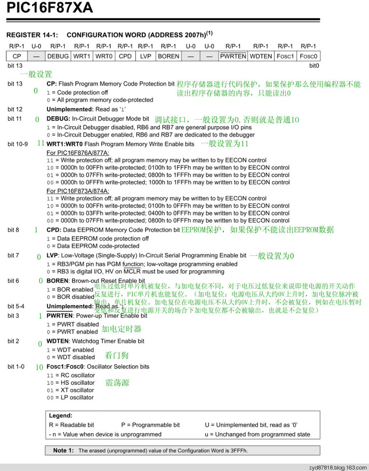
总结:我们可以根据编译器的文档说明来自己编写配置位,也可以使用IDE来自动生成。推荐使用自动生成的配置位代码。

评论