CAT6500自动电源选择开关应用指南

简介:
本文引用地址:https://www.eepw.com.cn/article/258547.htmThis document describes the application of the CAT6500power selector switch.Some portable systems require their battery to be chargedfrom two different power sources, like a computer USB portor an AC wall charger. Two different connectors allow toplug a USB cable or a wall charger. A dual input switchfunction can be achieved with a diode-OR circuit.
A bettersolution is to use MOSFET switches in order to minimize thevoltage drop (loss) and reduce the heat dissipation and theoverall component size.The CAT6500 integrates in a single IC two 3 A powerswitches as well as the control function. The very lowresistance (80 m_ typical) bidirectional switches allows thesystem battery to either be charged or power externalperipherals.
Another feature of the CAT6500 is to protect thesystem from high voltage transients up to 18 V coming fromthe external sources.
应用:
Figure 1 shows a typical application for a system with abattery and two separate charge sources. Once a powersource is plugged in, the CAT6500 automatically detects the voltage (if the supply greater than 1.7 V) on one of the two inputs PS1 or PS2 and provides the PWR_OUT output to thebattery charger IC.
If two sources are present at the sametime, the PRIORITY input allows to set a priority betweenthe PS1 and PS2.The CAT6500 operates in the “forward mode” when apower source is present on either PS1or PS2 and isconnected to the output PWR_OUT. The CAT6500 is abidirectional switch and can also operate in “reverse mode”where the PWR_OUT (battery voltage) can power or chargeexternal devices connected to PS1 and/or PS2 such as inUSB On-The-Go applications. The RM_EN1 and RM_EN2inputs set the reverse mode operation respectively on switchSw1 or Sw2.An internal overvoltage circuit protects the CAT6500 andany IC connected to the output PWR_OUT. As soon as eitherPS1 or PS2 input exceeds 7 V typical, PWR_OUT isdisconnected from the power source.No external components are required except for a small 1uF capacitor on the C1 pin. Optionally two open-drainoutputs SW1_STAT and SW2_STAT allow to read the status(on or off) for each of switches.
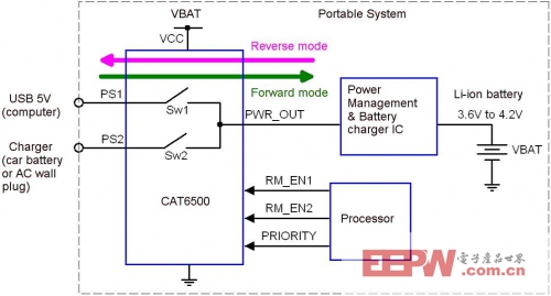
Figure 1. System Power Block Diagram
AND9051
A CAT6500 evaluation board is available to facilitate thedesign of the power selector switch into the application. Theboard schematic is shown in Figure 2. Two external powersources can be connected onto the PS1 and or PS2 terminals.The output PWR_OUT can be tied to the system powermanagement or charger IC or to a resistive load to simulatea battery charger. For more details, please refer to theCAT6500 Evaluation Board User’s Manual.Figure 2.
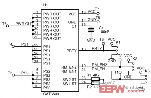
Figure 2. CAT6500 Evaluation Board Schematic
CAT6500技术方案、应用案例、电路图集锦
涵盖了CAT6500的技术方案和CAT6500的应用笔记以及CAT6500的电路图,为工程师学习CAT6500提供了一站式学习环境。

评论