基于CC430设计的超低功耗MCU射频应用方案

CC430系列是TI公司的集成了RF收发器的超低功耗MCU系统级芯片(SoC),器件具有功能强大的MSP430™ 16位RISC CPU,16位居寄存器,以及常数发生器,以得到最高的代码效率.工作电压1.8V-3.6V,CPU工作时的功耗160 µA/MHz,主要用在建筑物自动化,测试测量和财产跟踪.本文介绍CC430主要特性, CC430F613x和CC430F513x的功能方框图, 小于1GHz无线电方框图,以及CC430F61xx和CC430F51xx的典型应用电路图与材料清单.
The Texas Instruments CC430 family of ultralow-power microcontroller system-on-chip with integrated RF transceiver cores consists of several devices featuring different sets of peripherals targeted for a wide range of applications. The architecture, combined with five low-power modes is optimized to achieve extended battery life in portable measurement applications. The device features the powerful MSP430™ 16-bit RISC CPU, 16-bit registers, and constant generators that contribute to maximum code efficiency.
The CC430 family provides a tight integration between the microcontroller core, its peripherals, software, and the RF transceiver, making these true system-on-chip solutions easy to use as well as improving performance.
CC430主要特性:
True System-on-Chip (SoC) for Low-Power Wireless Communication Applications
Wide Supply Voltage Range: 1.8 V to 3.6 V
Ultralow Power Consumption:
CPU Active Mode (AM): 160 µA/MHz
Standby Mode (LPM3 RTC Mode):2.0 µA
Off Mode (LPM4 RAM Retention): 1.0 µA
Radio in RX: 15 mA, 250kbps, 915MHz
MSP430 System and Peripherals
16-Bit RISC Architecture, Extended Memory, 50-ns Instruction Cycle Time
Wake-Up From Standby Mode in Less Than6 µs
Flexible Power Management System with SVS and Brownout
Unified Clock System with FLL
16-Bit Timer TA0, Timer_A with Five Capture/Compare Registers
16-Bit Timer TA1, Timer_A with Three Capture/Compare Registers
Hardware Real-Time Clock
Two Universal Serial Communication Interfaces
USCI_A0 supporting UART, IrDA, SPI
USCI_B0 supporting I2C, SPI
12-Bit A/D Converter With Internal Reference, Sample-and-Hold, and Autoscan Features (Only CC430F613x and CC430F513x) Comparator
The CC430 has one active mode and five software selectable low-power modes of operation. An interrupt event can wake up the device from any of the low-power modes, service the request, and restore back to the low-power mode on return from the interrupt program.
The following six operating modes can be configured by software:
• Active mode (AM)
– All clocks are active
• Low-power mode 0 (LPM0)
– CPU is disabled
– ACLK and SMCLK remain active, MCLK is disabled
– FLL loop control remains active
• Low-power mode 1 (LPM1)
– CPU is disabled
– FLL loop control is disabled
– ACLK and SMCLK remain active, MCLK is disabled
• Low-power mode 2 (LPM2)
– CPU is disabled
– MCLK and FLL loop control and DCOCLK are disabled
– DCO’s dc-generator remains enabled
– ACLK remains active
• Low-power mode 3 (LPM3)
– CPU is disabled
– MCLK, FLL loop control, and DCOCLK are disabled
– DCO’s dc-generator is disabled
– ACLK remains active
• Low-power mode 4 (LPM4)
– CPU is disabled
– ACLK is disabled
– MCLK, FLL loop control, and DCOCLK are disabled
– DCO’s dc-generator is disabled
– Crystal oscillator is stopped
– Complete data retention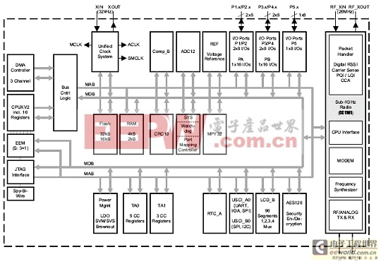
图1.CC430F613x功能方框图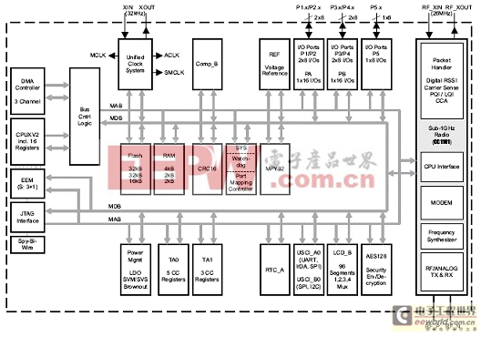
图2. CC430F612x功能方框图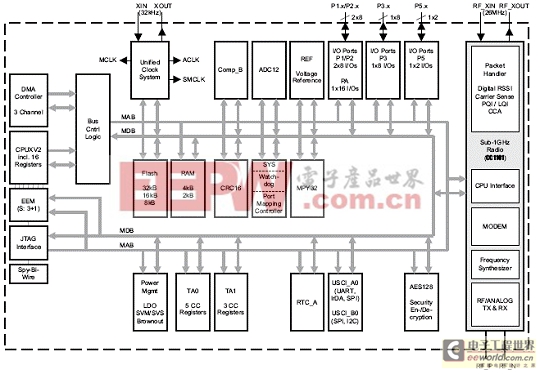
图3. CC430F513x功能方框图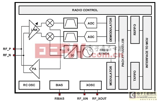
图4. 小于1GHz无线电方框图
图5. CC430F61xx典型应用电路图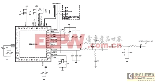
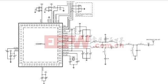
图6. CC430F51xx典型应用电路图
应用电路图材料清单:


评论