Implementing a MAX1385-Based C

When used with the MAX1385EVKIT+ demo board, the control loop achieves a regulation accuracy of ±2%. This accuracy is limited by the gate driver output step size and the FET transconductance. Drain-current regulation step size is determined by the MAX1385's gate-voltage increment multiplied by the FET's effective transconductance. Because the MAX1385EVKIT uses an IRFZ44N MOSFET to close the loop for demonstration purposes, the regulation may not be the same as it would be when used with an LDMOS FET.
Required Hardware
- Maxim MAX1385EVKIT+
- Maxim CMAXQUSB+ (includes USB A-B cable)
- Windows 2000/XP PC with USB port
- 5VDC at 100mA power supply
- 10VDC at 1000mA power supply
- DMM for measuring drain current
- DMM for measuring drain voltage
- DMM for measuring PGAOUT amplified current-sense voltage
- Optional: oscilloscope for monitoring GATE1 voltage and PGAOUT1 drain current
Setup
Download and unzip the necessary executable and source code files (ZIP, 736kB).Assemble the hardware according to Figure 1.
- Plug the CMAXQUSB header P3 into the MAX1385EVKIT connector J1.
- Connect the MAX1385EVKIT's DRAIN1 and DRAIN2 pins to the current meter (-).
- Connect the current meter (+) to the power supply (+).
- Connect the MAX1385EVKIT's SOURCE1 and SOURCE2 pins to the power supply (-).
- Connect the voltage meter (+) to the MAX1385EVKIT's DRAIN1 pin.
- Connect the voltage meter (-) to the MAX1385EVKIT's SOURCE1 pin.
- Connect the MAX1385EVKIT's AVDD pin to the DVDD pin (or, optionally, connect to an external 5V DC supply).
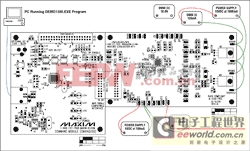
More Detailed Image (PDF, 387kB)
Figure 1. MAX1385EVKIT hardware configuration.
Procedure
Set the CMAXQUSB's VDD Select jumper to the 5V position.Connect the CMAXQUSB to the PC's USB port. If this is the first time a CMAXQUSB has been attached to the PC, the plug-and-play wizard will appear. Guide the GUI to the installed location of the device driver, in MAX1385_Appnote_src.zipsrcUSB_driver.
Start the DEMO1385.EXE program. A console will appear on the screen. Enter the following series of commands at the console:
| Command | Action |
| C | Connects to the CMAXQUSB module. Verify that the software reports: Board connected.Got board banner: Maxim CMAXQUSB V01.04.32 >Searching for MAX1385...Found MAX1385 at 0x4eNote: when using MAX1385EVKIT with CMAXQUSB,connect 5V DVDD supply to AVDD. |
| T V P | Test menu/verify power-up values |
| T S O FCT1 0300 | Test menu/servo mode/output register/FineCalThru1 register, initial value 0x0300 |
| T S I FF | Test menu/servo mode/input register/FIFO register |
| T S A 2 | Test menu/servo mode/ADC command/trigger channel 2 (current CS1) |
| T S T 0020 | Test menu/servo mode/target value 0x0020 |
| T S C 1 | Test menu/servo mode/convergence step positive 1 |
| T S H 1 | Test menu/servo mode/hysteresis one step |
| T S M 60000 | Test menu/servo mode/maximum loop duration set to 60 seconds |
| T S R | Test menu/servo mode/run |
| T W FCT1 0300 | Test menu/write register/FineCalThru1 register, value 0x0300 |
Monitor the regulation by watching the DMM.
The voltage on PGAOUT1 regulates between 20.8mV and 21.7mV, which is a variation of 0.45mV (2%) around an average of 21.25mV.
Source Code Walk-Through
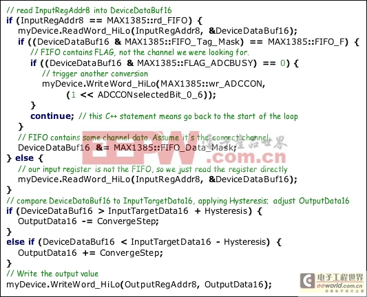
The source code was developed with the free dev-cpp IDE, which uses the GNU gcc-3.4.2 C++ compiler.Listing 1 shows a simplified version of the C++ code performed inside the regulation loop. Output statements and error handling have been removed for clarity.
Listing 1. Simplified C++ code.
Menu System
The complete source code implements the console menu system seen in Listing 2, which connects to the CMAXQUSB module.Listing 2. Console menu system.
============================================================CmodComm test program main menu when not connectedA) adjust timing parametersL) CmodLog... functionsC) connectD) Debug MessagesX) exit---------------------------------------------CBoard connected.Got board banner: Maxim CMAXQUSB V01.04.32 >Searching for MAX1385...Found MAX1385 at 0x4eNote: when using MAX1385EVKIT with CMAXQUSB,connect 5V DVDD supply to AVDD.============================================================CmodComm test program main menu after successful connectT) Test the device8) CmodP8Bus... functionsA) adjust timing parametersL) CmodLog... functionsP) CmodPin... functionsS) CmodSpi... functionsM) CmodSMBus... functions$) CmodCommStringWrite list of hex codesR) CmodBoardResetD) Disconnect============================================================T Test menuT ? Hunt for active devicesT R Read registerT W Write registerT S Servo loopT VP Verify Power-On Register ValuesT VM reg mask Verify Register Memory Persistence, All Combinations ...T VW reg mask Verify Register Memory Persistence, Walking-One's test ...============================================================Write register:T W AD Write ADCCONT W AH Write ALMHCFGT W AS Write ALMSCFGT W FI1 Write FINE1T W FI2 Write FINE2T W FC1 Write FINECAL1T W FC2 Write FINECAL2T W FCT1 Write FINECALTHRU1T W FCT2 Write FINECALTHRU2T W FT1 Write FINETHRU1T W FT2 Write FINETHRU2T W HC Write HCFGT W HT1 Write THRUHI1T W HT2 Write THRUHI2T W HW1 Write HIWIPE1T W HW2 Write HIWIPE2T W IH1 Write IH1T W IH2 Write IH2T W IL1 Write IL1T W IL2 Write IL2T W LD Write LDACT W LT1 Write THRULO1T W LT2 Write THRULO2T W LW1 Write LOWIPE1T W LW2 Write LOWIPE2T W P Write PGACALT W SC Write SCLRT W SS Write SSHUTT W TH1 Write TH1T W TH2 Write TH2T W TL1 Write TL1T W TL2 Write TL2T W X /hexRegAddr/ Write any register by its hexadecimal address============================================================Read register:T R AH Read ALMHCFGT R AS Read ALMSCFGT R FF Read FIFOT R FI1 Read FINE1T R FI2 Read FINE2T R FL Read FLAGT R HC Read HCFGT R HW1 Read HIWIPE1T R HW2 Read HIWIPE2T R IH1 Read IH1T R IH2 Read IH2T R IL1 Read IL1T R IL2 Read IL2T R LW1 Read LOWIPE1T R LW2 Read LOWIPE2T R TH1 Read TH1T R TH2 Read TH2T R TL1 Read TL1T R TL2 Read TL2T R X /hexRegAddr/ Read any register by its hexadecimal address============================================================T S Test Servo menuT S O FCT1 0300 output register [wr_FINECALTHRU1, initial value 0x0300]T S I FF input register [rd_FIFO]T S A 2 ADC input channel [ bit 2 = 0x0004 = ADCCON_CURRENT_CS1 ]T S T 0020 target value [0x0020]T S C 1 ConvergeStep [1]T S H 1 hysteresis [1]T S M 60000 max_loop_duration_msec [60000]T S R servo loop run============================================================
Windows is a registered trademark of Microsoft Corp.


评论