3节镍氢电池充电电路图

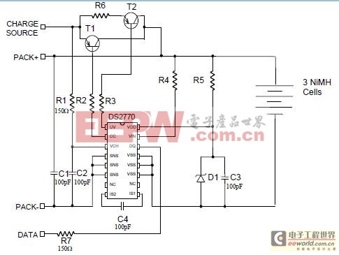
Figure 1 contains the recommended schematic for charging a 3-cell NiMH battery pack. Refer to Application Note 201 for the values of all the components shown in the schematic. In addition to following this schematic, there are some other things to consider when completing the application design.
The charge source for the application should be a constant current or current limited supply with an opencircuit voltage between 5V and 12V. The current supplied by the charge source must be large enough to sufficiently heat the battery pack when a full charge is reached, otherwise, the cells heat too slowly to trip the dT/dt primary charge termination limit. Consequently, charge termination is always reliant on a
secondary criteria such as exceeding a maximum temperature or a maximum charge time.In order to assure charging will terminate as a result of dT/dt primary termination limit, the DS2770 should be placed close to the battery cells with good thermal contact. It may be necessary to include thermally conductive putty between the cells and the DS2770 to enable efficient heat transfer.
Additionally, enclosing the cells and the DS2770 in a casing allows the heat generated by the cells as they charge to be transferred to the DS2770 before it is lost to the ambient conditions.


评论