击落模型定位器电路 (Downed Model Locato

击落模型定位器电路 (Downed Model Locator)

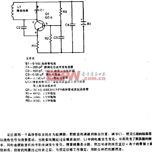
If you know people who fly slope gliders frequently, you probably know someone who has lost a glider in the weeds or bushes. Here is a circuit I've shamelessly swiped from George Steiner's book "A to Z - Radio Control Electronic Journal" that may help you find your glider. I modified the circuit to use parts currently available at your local Radio Shack store, and modified it to decrease false triggering from low voltage spikes in the on-board power system when full sized or higher torque servos are used.
Your transmitter sends a set of pulses to your receiver every 20 milliseconds, and your receiver in turn sends an individual pulse to each of your servos at the same interval. This circuit is a pulse omission detector--an alarm sounds when the pulses, originating from your transmitter, are no longer present. By plugging this circuit into an unused servo socket on your receiver, you can turn on the alarm by turning off your transmitter.
The first capacitor C1 filters out DC voltage, preventing an aggressive automatic gain control of some current receivers from shutting off the alarm even when your transmitter is off. The first transistor Q1 serves to flip the pulse to negative modulation that the 555 needs. The C2 capacitor and the R4 resistor establish the time interval--if no pulse is received in the time it takes to charge the capacitor through the resistor, the alarm sounds. The interval is the resistance multiplied by the capacitance: 1uF x 47k = 0.000001F x 47000 ohms = 0.047sec = 47msec which is a little over twice the standard 20msec R/C frame rate--this device uses a little longer interval than the frame rate to prevent false triggering. The other capacitor C3 smoothes the control voltage on the 555, preventing false triggering from spikes in the supply voltage. Unless a pulse opens the Q2 transistor to drain the C2 capacitor before the capacitor is fully charged, the pin 6 threshold senses a high voltage and triggers the output pin 3 to go low, sinking current across the buzzer and making noise. With the reset pin 4 high, the discharge pin 7 drains the capacitor, and the cycle starts again.


The circuit draws 1mA (!) when idle and 4 mA when buzzing. I've been using large peizo buzzers (see part numbers below) because they are light and loud, and the 6 volt electromagnetic buzzer where weight is not so much of a concern.
The circuit uses your receiver battery for power. For the ultimate in reliability, you can use an additional battery to supply the alarm as follows. Connect only signal and negative leads to your receiver socket, and connect the second battery positive to positive circuit lead and negative to negative circuit lead. You will need to put some kind of switch in series with the second battery to keep it from running the alarm when you are not flying. With the extra battery, you will still be able to find your plane if your plane went down because of a receiver battery failure, or if your receiver battery fell out in the crash. You can use a nine volt battery for this, but be careful to NOT connect the nine volt battery to your receiver--or you will smoke your receiver. Note: Do NOT solder to a button battery--they explode.
Here are few Radio Shack parts numbers. You can substitute other types of capacitors; tantalum capacitors are just physically smaller. Polarity of the tantalum capacitor probably does not matter at this low voltage (compared to the rated maximum voltage), but to be particular, the positive lead would be directed toward the input signal lead and away from the negative side. Power in this circuit is minimal and you can use the smallest resistors you can get your hands on (get 1/8 watt if you can, but any power rating will work).
273-065 peizo buzzer $2.99 273-054 electric buzzer $2.59 276-1604 2N3906-type PNP transistors, 15 per $2.29 276-2016 2N3904 NPN transistor $0.59 
相关推荐
技术专区


评论