交换位技术改进FPGA-PWM计数器性能

简单改变FPGA计数器规格使作为DAC功能PWM计数器的纹波降低。
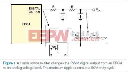
本文引用地址:https://www.eepw.com.cn/article/190557.htm当需要一些模拟输出和系统中有FPGA时,很可能选择使用如图1的PWM模块和简单低通滤波器。FPGA的输出是固定频率、计数器和数字比较器使占空比可变的典型波形(表1)。
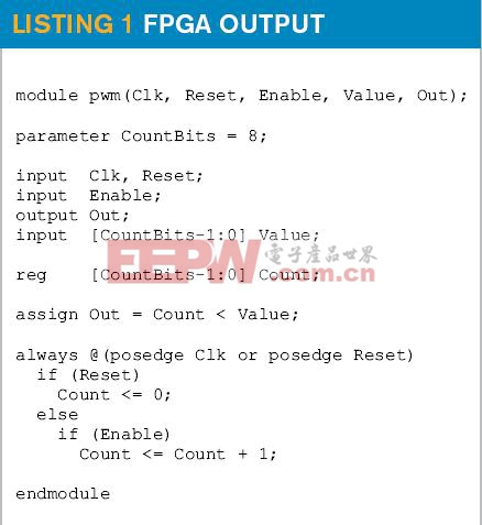
假设高信号使能,计数器每个时钟周期进行计数,PWM输出的频率为时钟频率的2次幂分频。通过连接前置比例器,使用使能来降低输出频率。由于输出频率固定,滤波器容易计算。已知占空比50%时,出现最坏的纹波。最大纹波和上升时间的限制结合决定滤波器类型和RC(电阻/电容)值。
对表1中编码进行非小改动,能够改进PWM电路的性能。但在原先系统中,最大纹波电流发生在50%占空比时,最小纹波电流发生在最小占空比时,改进的版本显示最大纹波等于标准版的最小值。关键是产生最高频率的可能性,还能保持平均的占空比常数。输出脉冲频率越高,滤波器性能越好。
从左到右交换所有位来修改由重编二进制比较器组成表1。MSB(最高有效位)变成LSB(最低有效位),LSB变成MSB,等等(表2)。只需重编位,而不需额外寄存器或逻辑单元。
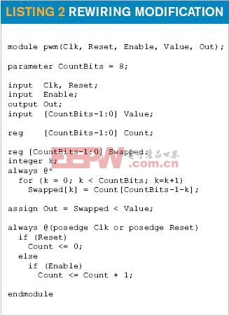
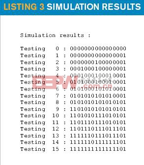
表3显示了4位PWM发出的脉冲序列。表3中,可以看到50%占空比时(第二列,值为8),频率最大,为时钟频率的2分频。在第一个纹波出现点(第二列,值为1),传统PWM系统中有同样的纹波,也就是说,脉冲序列是相同的。
英文原文:
Swapping bits improves performance of FPGA-PWM counter
A simple change to the specification of an FPGA counter lowers the ripple of a PWM counter functioning as a DAC.
Stefaan Vanheesbeke, Ledegem, Belgium; Edited by Charles H Small and Fran Granville -- EDN, 9/13/2007
When you need some analog outputs and you have an FPGA in your system, you probably choose to use a PWM module and a simple lowpass filter such as those in Figure 1. The output of the FPGA is typically a waveform with a fixed-frequency, variable-duty cycle, which a counter and a digital comparator generate (Listing 1).
Suppose that Enable is high, the counter counts up every clock cycle, and the frequency of the PWM output is the clock frequency divided by 2 count bits. You can use Enable to lower the output frequency by connecting it to a prescaler. Because the output frequency is fixed, the filter is easy to calculate, because you know that the worst-case ripple happens at a duty cycle of 50%. The combination of the desired maximum ripple and settling time determines the filter type and RC (resistance/capacitance) values.
With a small change to the code in Listing 1, you can improve the performance of the PWM circuit. Whereas in the original system, the maximum ripple currents occur at a duty cycle of 50% and the minimum ripple currents occur at the minimum duty cycle, the improved version shows a maximum ripple equal to the minimum of the standard version. The trick is to generate the highest frequency possible but keep the average duty cycle constant. The higher the frequency of the pulses on the output, the better the filter does its job.
The modification to Listing 1 consists of rewiring the binary comparator with all the bits swapped from left to right. The MSB (most significant bit) becomes the LSB (least significant bit), the LSB becomes the MSB, and so on (Listing 2). You do only a rewiring requiring no extra registers or logic.
Listing 3 shows the pulse trains that a 4-bit PWM emits. In Listing 3, you see that at 50% duty cycle (Value=8, second column), the frequency is maximum and equal to the clock frequency divided by two. At the first point at which some ripple shows up (Value=1, second column), there is exactly the same ripple as in the conventional PWM system—that is, the pulse train is the same.

pwm相关文章:pwm原理
尘埃粒子计数器相关文章:尘埃粒子计数器原理


评论