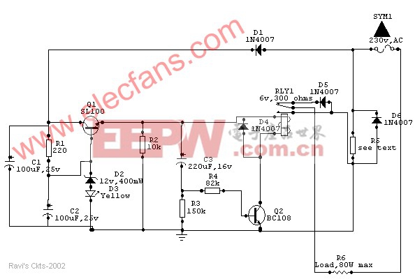
分立元件组成的烙铁电路

Wattage of load | 10W | 18W | 25W | 35W | 65W | 80W |
Value of R5 (in ohms) | 330 | 180 | 136 (68+68) | 100 | 56 | 44 (22+22) |
Wattage of R5 (in watts) | 01 | 02 | 02 | 04 | 05 | 6.5 |
Usually a soldering iron takes a couple of minutes to get adequately heated up to melt the solder, after which the heat generated is much above the requirement and is wasted. Moreover, excessive heat decreases the life of the bit and the element, causing serious damage to the components.
The above circuit solves this problem in a simple and inexpensive way and could be used to various types of loads up to 80watts.
How it works
Once the main is switched on, an approximate 15v drop of the positive half cycle across R5 is detected and supplied to Q1 (SL100 or D313), which acts as a voltage regulator. Zener diode D2 together with diode D3 (yellow LED) stabilizes the emitter voltage of Q1 at 13.2Vdc, which is then delivered to the relay circuit built around Q2 and C3. Capacitor C3 charges through the base-emitter path of Q2 and causes the relay to actuate, which in turn allows both the half cycles of the AC mains to flow through diode D6 and R5 to the load to heat it up at a normal rate.
After a certain lapse of time (about 2 minutes preset) C3 saturates and Q2 stops conducting through the relay, thus switching on series diode D5 to allow only half of the Ac cycle through the load.

DIY机械键盘相关社区:机械键盘DIY

评论