电压和电流反馈放大器几乎一致

电压和电流反馈放大器应用电路的结构一般相同,除了几个关键点。
电流反馈比电压反馈放大器有更高的转换速率。像这样,电流反馈比电压反馈放大器能更好的解决高速问题。“电流反馈放大器”的名字带有一些神秘色彩,但一般电流反馈和电压反馈放大器应用电路的结构是一致的,除了几个关键点。
首先,电流反馈放大器电路的反馈电阻值必须保持在小范围内。电阻值越低,电流反馈放大器的稳定性越差。可以在电流反馈放大器产品手册中找到规定的电阻值。电压反馈放大器的反馈电阻值更宽。放大器的驱动能力限制了电阻的最小值,全电路噪声限制电阻最大值。
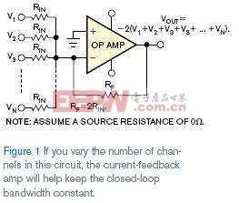
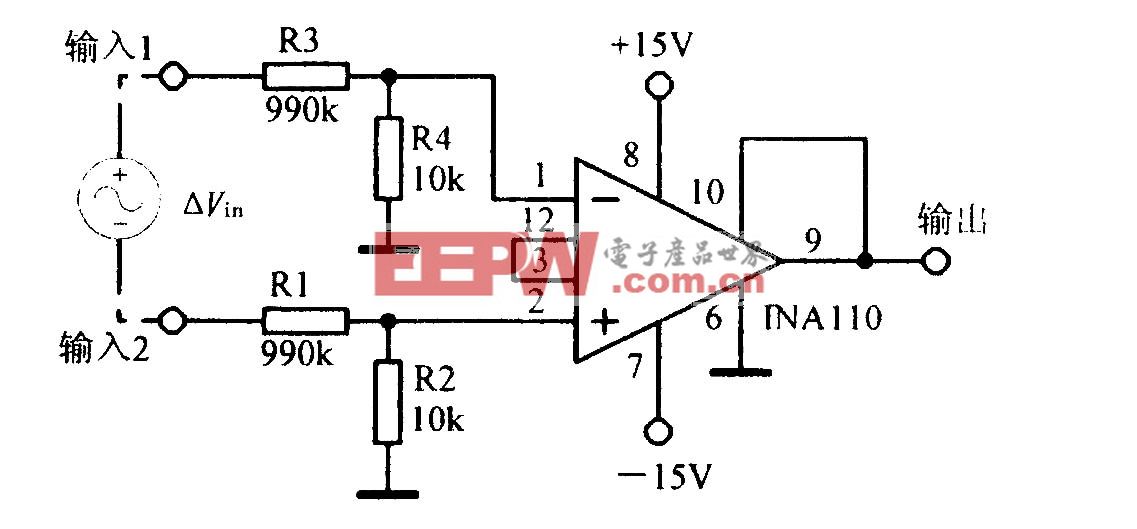
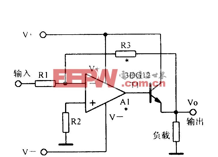
图1显示了适于电流或电压反馈放大器的电路。如果反馈电阻RF等于2RIN,其中RIN为输入电阻,各通道的闭环增益为–2V/V。乍看,容易假设闭环带宽与增益带宽积除以各通道的增益相等,或|–2V/V|。但千万别做这个假设!
如果使用如图1电路中电压或电流反馈放大器,噪声增益为:
![]()
其中,N为输入通道数。带电压反馈放大器的电路带宽等于增益带宽积除以噪声增益。例如,如果使用180MHz增益带宽积的电压反馈放大器,三个输入通道(N=3),增益–2V/V,电路闭环带宽为25.7 MHz。额外的通道减少闭环带宽,即使输入信号持续达到–2V/V的增益。
如果使用如图1电路的电流反馈放大器,放大器闭环带宽较少的依靠闭环增益和输入通道数。如果用这样的放大器设计电路,首先应该挑选合适的反馈电阻,各厂商的规格和电路噪声增益。然后选择合适的RIN值。从这一点,如果电路增加通道,或许将发生信号带宽和增益剧增的微小变化。如果那个情形出现,退回并确定反馈电阻的选择。对电流和电压反馈放大器,噪声增益通常与公式1的结果相等,但减少电流反馈放大器电路的反馈电阻值,使电路带宽增加。
英文原文:
Voltage- and current-feedback amps are almost the same
The application-circuit configurations for voltage- and current-feedback amps are generally the same, except for a few key points.
By Bonnie Baker -- EDN, 10/25/2007
Current-feedback amplifiers have a higher slew rate than do voltage-feedback amplifiers. As such, current-feedback amps can better solve high-speed problems than their voltage-feedback counterparts. The name “current-feedback amp” carries some mystique, but, generally, the application-circuit configurations for voltage- and current-feedback amps are the same, except for a few key points.
First, the feedback resistor of a current-feedback-amp circuit must stay within a small range of values. Lower value resistors reduce the current-feedback amp’s stability. The feedback resistor’s higher values reduce the current-feedback amp’s bandwidth. You can find the prescribed feedback-resistor value in the current-feedback amp’s product data sheet. The voltage-feedback-amp’s feedback-resistance value is more forgiving. This amplifier’s drive capability limits the resistor’s minimum value, and the overall circuit noise limits the maximum value.
Figure 1 sho ws a circuit that is appropriate for either a current- or a voltage-feedback amp. If the feedback resistance, RF, equals 2RIN, where RIN is the input resistance, the closed-loop gain of each channel is –2V/V. At first glance, it is easy to assume that the closed-loop bandwidth equals the gain-bandwidth product divided by each channel’s gain, or |–2V/V|. Don’t make this assumption!
If you use a voltage- or current-feedback amp with the circuit in Figure 1, the noise gain is:
where N is the number of input channels. This circuit’s bandwidth, with a voltage-feedback amp, equals the gain-bandwidth product divided by the noise gain. For instance, if you have a voltage-feedback amp with a gain-bandwidth product of 180 MHz and there are three input channels (N=3) at a gain of –2V/V, the circuit’s closed-loop bandwidth is 25.7 MHz. Additional channels reduce the closed-loop bandwidth, even though the input signals continue to see a gain of –2V/V.
If you use a current-feedback amp with the circuit in Figure 1, the amplifier’s closed-loop bandwidth depends less on the closed-loop gain and the number of input channels. If you design this circuit with such an amp, you would first pick the optimum feedback resistor, per the manufacturer’s specification and the circuit’s noise gain. You would then select the appropriate value for RIN. From this point, if you add channels to the circuit, a small variation in the signal bandwidth and gain peaking in circuit may occur. If that scenario is a concern, go back and refine your feedback-resistor selection. For both current- and voltage-feedback amps, the noise gain always equals the result of Equation 1, but you can reduce the feedback-resistor value with the current-feedback-amp circuit and get an increase in circuit bandwidth.

基尔霍夫电流相关文章:基尔霍夫电流定律


评论