简单的检测电路降低LED驱动电源线调光

A modification of the current-control circuit in a low-voltage LED system allows use of a chopped supply voltage to modulate the LED intensity. The circuit prevents inrush current to the decoupling capacitors by turning off the LEDs during intervals when the supply voltage is off.
In low-voltage (24V) lighting systems, the off-line power supplies can often be located at some distance from the lamps. A simple two-wire cable usually connects the two sections, and the lamp intensity can be controlled by chopping the supply voltage. For filament-based lights this is not a problem, but a chopped supply voltage can affect the reliability of LED lamps.
LED lamps require a dedicated circuit for controlling the LED current, and like most control circuits, this one requires a decoupling capacitor at the supply-voltage input. The capacitor alternately charges and discharges with each transition of the supply voltage, and ceramic capacitors can produce an annoying acoustic noise when treated this way. Electrolytic capacitors don't have the acoustic problem, but high inrush currents can cause power dissipation in the equivalent series resistance, which affects reliability. (ESR for electrolytics is higher than that of ceramic capacitors.) This effect can reduce the lifetime of an electrolytic capacitor.
You can avoid discharging the decoupling capacitors by simply switching the LEDs off during the supply-voltage off time. Most LED drivers (such as the MAX16832) have a dedicated input (DIM) that can be used to switch the LED current on and off rapidly. But, you must drive the DIM input with an extra signal, which cannot be done if only two wires are available! The solution is to have the LED-driver circuit in the lamp detect the start of the off-time, and turn off the LEDs before the capacitors are heavily discharged. This circuit must also detect the start of on-time, so it can turn the LEDs back on.
The simplest implementation of this idea is shown in Figure 1 (ignore the blue lines for the moment). Diode D (in red) isolates the DIM signal from the decoupling capacitor. When the supply voltage turns off (i.e., the off-time starts), the DIM signal goes to logic zero and disables the LED driver. Because the decoupling capacitor is no longer loaded by the LEDs, it retains its charge.
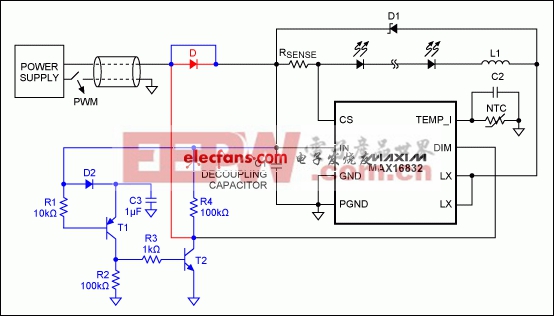
Figure 1. This circuit, including the circuitry in blue and without the diode in red (see text) prevents excessive charging and discharging of the decoupling capacitor by turning off the LEDs during intervals when the chopped supply voltage is off.
In practice, this approach has several drawbacks. First, the diode introduces dissipation equal to Vƒ × ILOAD. Second, the exact moment the driver switches off is determined by capacitance in the system before the diode. If this capacitance is significant, the DIM signal will not drop instantly, but will take some time to reach logic zero, and this time interval can allow the decoupling capacitor to lose a lot of charge. The problem can be overcome with a load resistor to ground just before the diode, which rapidly pulls the DIM signal to ground, but that resistor also introduces unwanted dissipation during the on-time.
A better solution is demonstrated by the additions in blue shown in Figure 1. The diode is eliminated, and the combination of D2/C3 forms an envelope detector that follows the input voltage, but slowly. During on-time the base-emitter voltage of T1 is positive, so T1 is off and its collector is at 0V. T2, R3, and R4 form an inverter that converts this logic 0 to logic 1, turning on the LEDs via the DIM pin.
The input voltage drops rapidly with the start of off-time, but the envelope detector responds more slowly. As a result, the base voltage on T1 drops faster than its emitter voltage. T1 switches on when the base-emitter voltage reaches -0.7V, causing the logic level at DIM to change from 1 to 0. This transition switches off the LED driver instantly, thereby removing the load from the decoupling capacitor. The base voltage goes up again as on-time begins, switching T1 off and the LED driver back on. Because input-voltage fluctuations are not much more than 1V, inrush currents at the start of on-time are much reduced.
These performance improvements are easily measurable. First, the waveforms of Figure 2a show the effect of a chopped input voltage with no measures taken to protect the decoupling capacitor. Inrush currents show peaks larger than 12A, and the input voltage (present on the decoupling capacitor) exhibits large oscillations. During off-time, the input voltage drops by more than 10V.
Introducing the detection circuit greatly reduces these values (Figure 2b). Input current peaks are roughly 2A, a factor-of-6 improvement. The input voltage shows much less fluctuation—now on the order of 2V, which is low enough to allow the use of inexpensive ceramic decoupling capacitors without audible noise. The DIM signal (Figure 3) shows two glitches due to oscillations on the input voltage: one at the beginning of the on-period, and a smaller one at the beginning of the off-period. These glitches are too short, however, to affect the LED current (Figure 4).
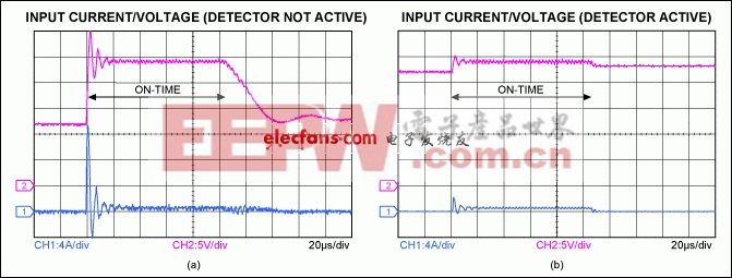
Figure 2. Input voltage and current from Figure 1, with the blue detection circuit inactive (a) and active (b).
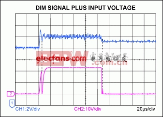
Figure 3. In Figure 1, oscillation on the input voltage (blue) causes glitches at the DIM-voltage transitions.
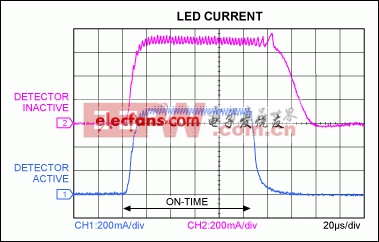
Figure 4. These LED-current waveforms from Figure 1 show that an active detector circuit (blue trace) has little effect on the LED current.

DIY机械键盘相关社区:机械键盘DIY


评论