DIY Arduino万向节|自稳平台

在本教程中,我们将学习如何建立一个Arduino万向节或一个带有伺服电机的自稳定平台。本教程实际上是先前关于 .
概述
我用三维建模软件设计了万向节。它由3台MG996R伺服电机组成,用于3轴控制,以及MPU6050传感器、Arduino和电池的底座。
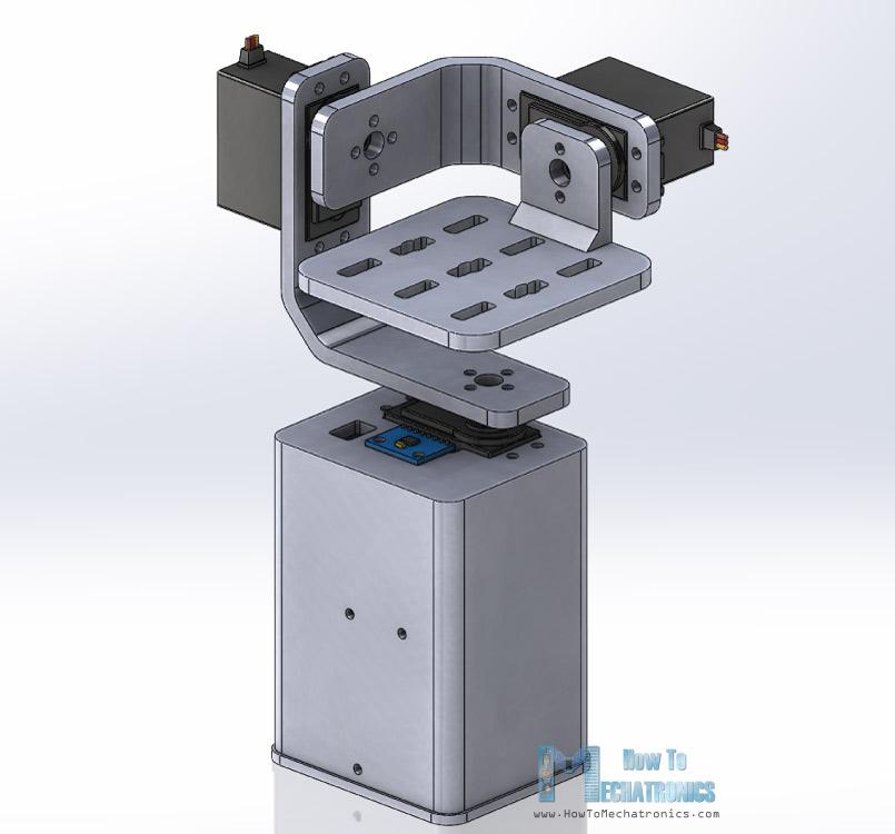
您可以在以下位置找到并下载此三维模型以及用于三维打印的STL文件:
使用我的,我3D打印了所有的部件,它们都非常完美。
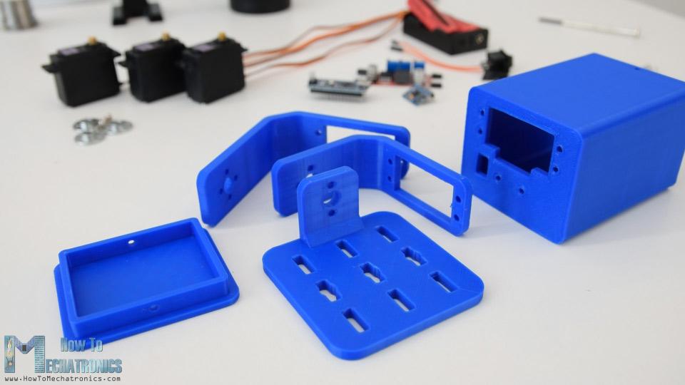
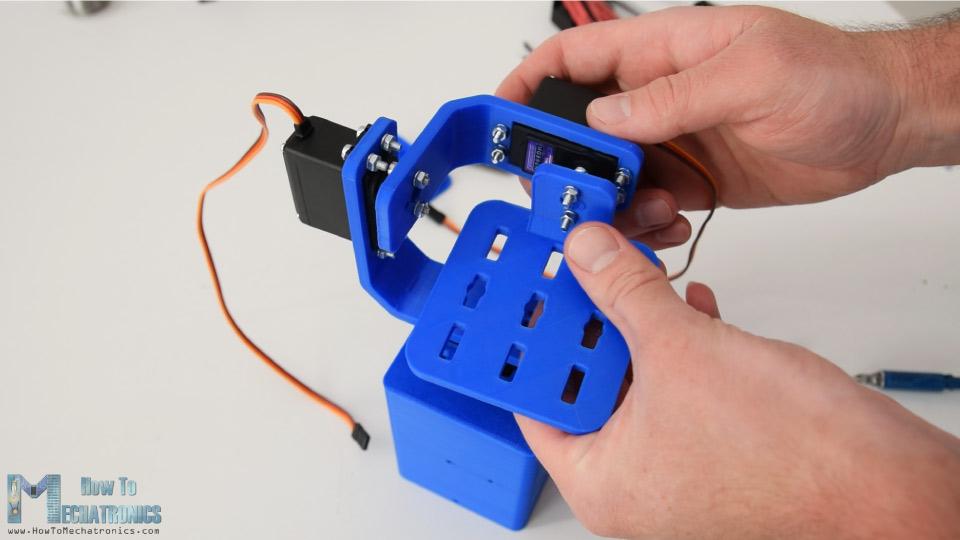
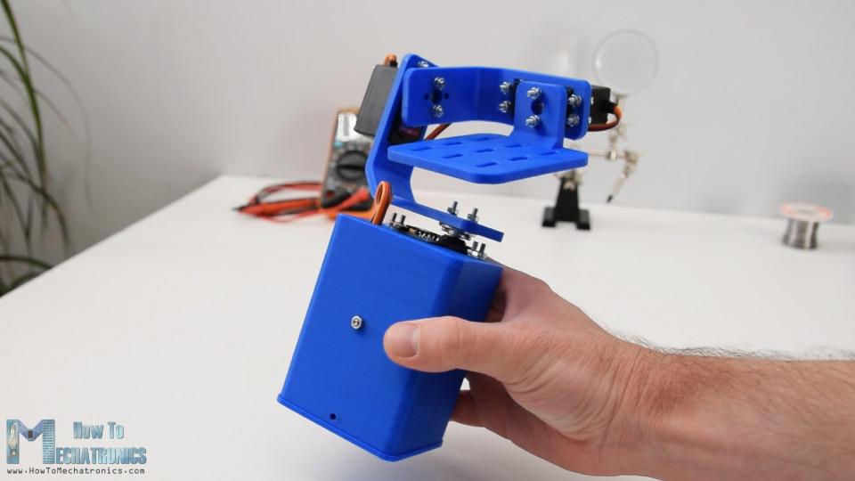
装配
组装万向节很容易。我从安装偏航伺服开始。我用M3螺栓和螺母把它固定在底座上。
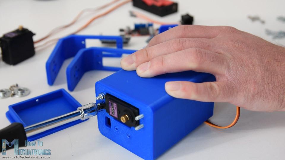
下一步,我用同样的方法固定了滚动伺服。这些零件是专门设计的,以方便安装MG996R伺服系统。
为了将零件相互连接,我使用了圆喇叭,它作为伺服系统的附件。
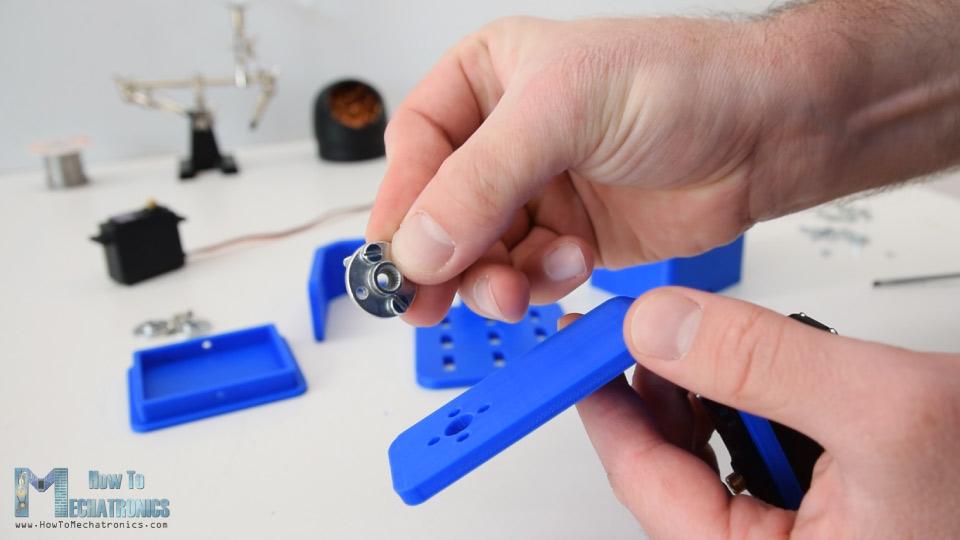
首先,我们需要用两个螺栓将圆喇叭固定在底座上,然后用另一个螺栓将其连接到之前的伺服系统上。
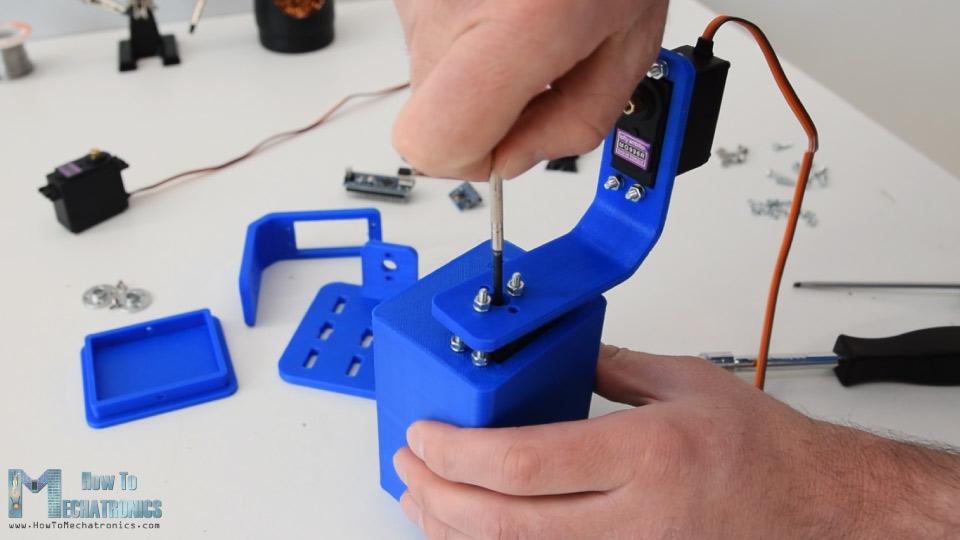
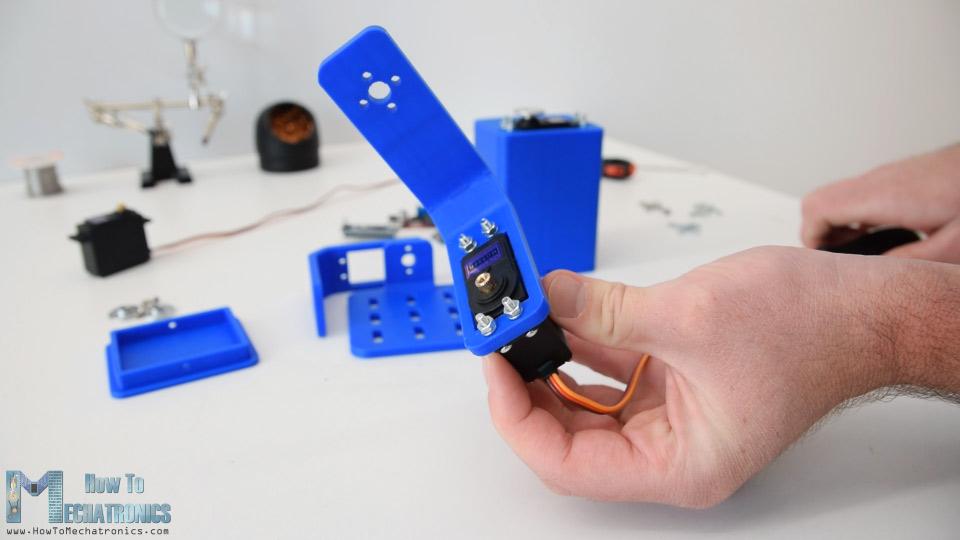
我重复了这个过程,组装其余的组件,变桨伺服和顶部平台。
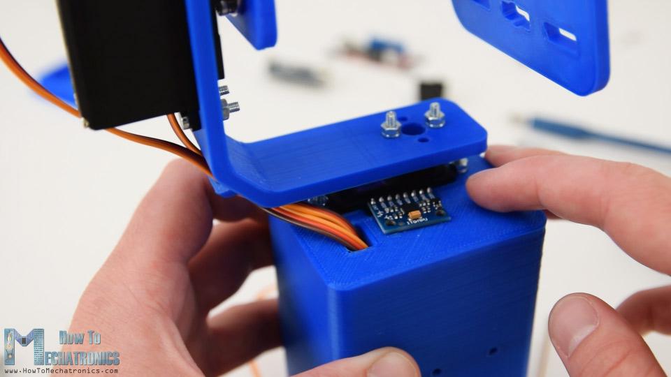
下一步,我通过伺服线通过支架的开口,以保持他们的组织。然后我插入MPU6050传感器,用螺栓和螺母将其固定在底座上。
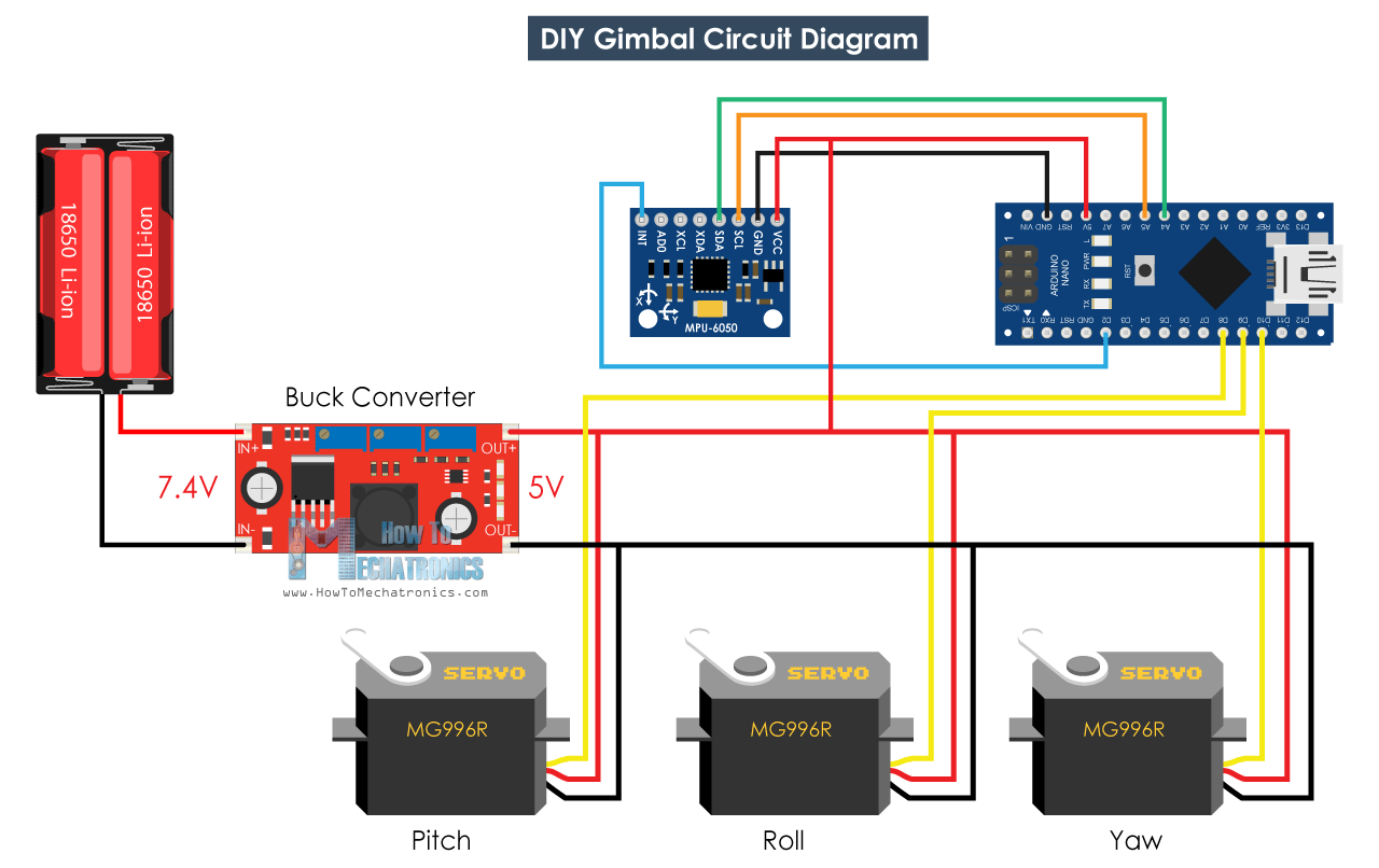
为了给这个项目供电,我用了2节锂离子电池,我把它们放在这个电池架上。我用两个螺栓和螺母把电池座固定在底座上。
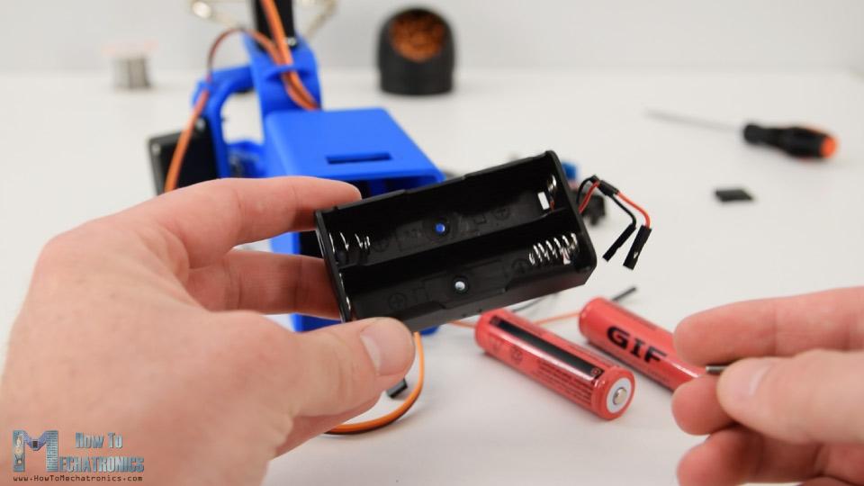
2节锂离子电池将产生约7.4V的电压,但我们需要5伏的电压来为Arduino和伺服系统供电。
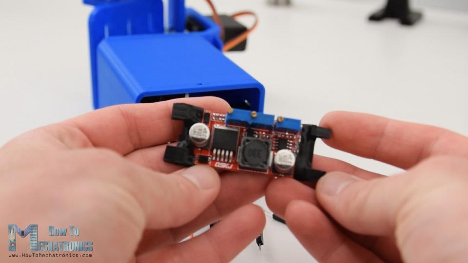
这就是为什么我使用了一个降压转换器,将7.4伏转换为5伏。
Arduino万向节电路图
现在剩下的,就是把一切联系起来。这里的电路图和所有的电路图都需要连接起来。
您可以从以下链接获取本Arduino教程所需的组件:
MPU6050 IMU
MG996R伺服
降压转换器
Arduino Uno
试验板和跨接导线
最后,我把电子元件和电线压入底座,用底部的盖子盖住它们。
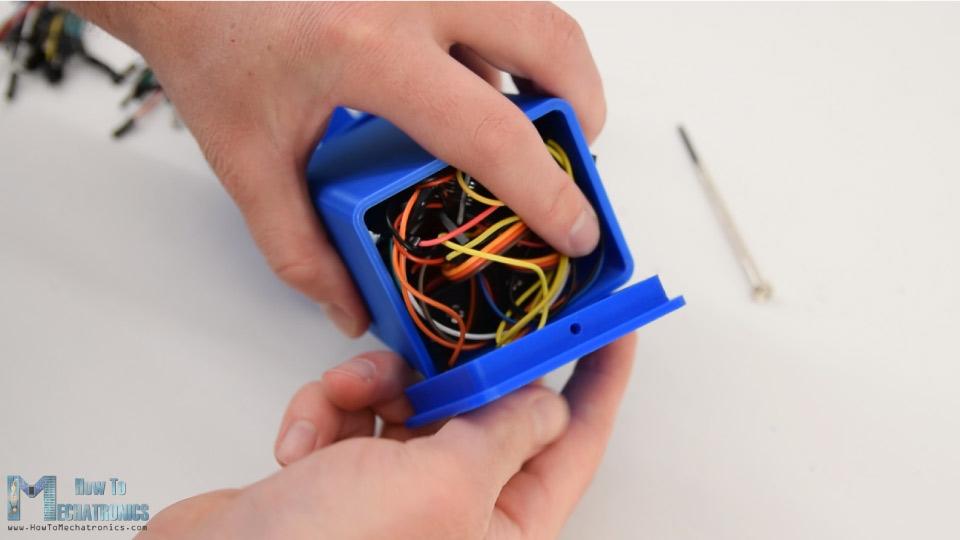
有了这个,自平衡平台或Arduino万向节就完成了,它的工作和预期一样好。剩下的就是看看程序。
Arduino代码
本例中的Arduino代码是对MPU6050 U DMP6示例的修改 .
代码说明:所以,我们使用输出可读的偏航,俯仰和横摇。
// Get Yaw, Pitch and Roll values
#ifdef OUTPUT_READABLE_YAWPITCHROLL
mpu.dmpGetQuaternion(&q, fifoBuffer);
mpu.dmpGetGravity(&gravity, &q);
mpu.dmpGetYawPitchRoll(ypr, &q, &gravity);
// Yaw, Pitch, Roll values - Radians to degrees
ypr[0] = ypr[0] * 180 / M_PI;
ypr[1] = ypr[1] * 180 / M_PI;
ypr[2] = ypr[2] * 180 / M_PI;
// Skip 300 readings (self-calibration process)
if (j <= 300) {
correct = ypr[0]; // Yaw starts at random value, so we capture last value after 300 readings
j++;
}
// After 300 readings
else {
ypr[0] = ypr[0] - correct; // Set the Yaw to 0 deg - subtract the last random Yaw value from the currrent value to make the Yaw 0 degrees
// Map the values of the MPU6050 sensor from -90 to 90 to values suatable for the servo control from 0 to 180
int servo0Value = map(ypr[0], -90, 90, 0, 180);
int servo1Value = map(ypr[1], -90, 90, 0, 180);
int servo2Value = map(ypr[2], -90, 90, 180, 0);
// Control the servos according to the MPU6050 orientation
servo0.write(servo0Value);
servo1.write(servo1Value);
servo2.write(servo2Value);
}
#endif
一旦我们得到这些值,首先我们把它们从弧度转换成度。
// Yaw, Pitch, Roll values - Radians to degrees
ypr[0] = ypr[0] * 180 / M_PI;
ypr[1] = ypr[1] * 180 / M_PI;
ypr[2] = ypr[2] * 180 / M_PI;
然后我们等待或读取300个读数,因为在此期间传感器仍处于自校准过程中。另外,我们捕捉偏航值,它在开始时不像俯仰和横摇值为0,而是总是一些随机值。
// Skip 300 readings (self-calibration process)
if (j <= 300) {
correct = ypr[0]; // Yaw starts at random value, so we capture last value after 300 readings
j++;
}
在300个读数之后,首先我们通过减去上面捕获的随机值将偏航设置为0。然后我们将偏航、俯仰和横摇的值从-90度映射到0到180度,这些值用于驱动伺服系统。
// After 300 readings
else {
ypr[0] = ypr[0] - correct; // Set the Yaw to 0 deg - subtract the last random Yaw value from the currrent value to make the Yaw 0 degrees
// Map the values of the MPU6050 sensor from -90 to 90 to values suatable for the servo control from 0 to 180
int servo0Value = map(ypr[0], -90, 90, 0, 180);
int servo1Value = map(ypr[1], -90, 90, 0, 180);
int servo2Value = map(ypr[2], -90, 90, 180, 0);
// Control the servos according to the MPU6050 orientation
servo0.write(servo0Value);
servo1.write(servo1Value);
servo2.write(servo2Value);
}
最后利用写函数,把这些值作为控制信号发送给伺服系统。当然,你可以禁用偏航伺服,如果你只想稳定的X和Y轴,并使用这个平台作为相机常平架。
请注意这远不是好的相机万向节。运动不平稳,因为这些伺服不是为了这样的目的。真正的相机万向节使用一种特殊类型的为了获得流畅的动作。所以,考虑这个项目只是为了教育目的。
*博客内容为网友个人发布,仅代表博主个人观点,如有侵权请联系工作人员删除。