带低音增强的立体声前置放大器电路 (Stereo Pream

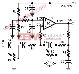
带低音增强的立体声前置放大器电路 (Stereo Preamplifier with Bass-boost)
gh Quality, simple design 20 to 30V supply
Parts:
P1_________________10K Log.Potentiometer (Dual-gang for stereo)
P2________________100K Log.Potentiometer (Dual-gang for stereo) (See Notes)
R1,R2_____________100K 1/4W Resistors
R3,R6______________15K 1/4W Resistors
R4_________________10K 1/4W Resistor
R5_________________22K 1/4W Resistor
R7__________________1K 1/4W Resistor
R8________________560R 1/4W Resistor
C1,C2,C5____________2΅2 63V Electrolytic Capacitors
C3________________470΅F 35V Electrolytic Capacitor
C4__________________1΅F 63V Polyester Capacitor
C6_________________47nF 63V Polyester Capacitor
C7_________________22΅F 25V Electrolytic Capacitor
IC1_______________TL072 Dual BIFET Op-Amp
SW1________________DPST Switch (Optional, see Notes)
Comments:
This preamplifier was designed to cope with CD players, tuners, tape recorders etc., providing a gain of 4, in order to drive less sensitive power amplifiers. As modern Hi-Fi home equipment is frequently fitted with small loudspeaker cabinets, the bass frequency range is rather sacrificed. This circuit features also a bass-boost, in order to overcome this problem. You can use a variable resistor to set the bass-boost from 0 to a maximum of +16dB @ 30Hz. If a fixed, maximum boost value is needed, the variable resistor can be omitted and substituted by a switch.
Notes:
Schematic shows left channel only, but R1, R2, R3 and C1, C2, C3 are common to both channels.
For stereo operation P1, P2 (or SW1), R4, R5, R6, R7, R8 and C4, C5, C6, C7 must be doubled.
Numbers in parentheses show IC1 right channel pin connections.
A log type for P2 ensures a more linear regulation of bass-boost.
Needing a simple boost-in boost-out operation, P2 must be omitted and SW1 added as shown in the diagram.
For stereo operation SW1 must be a DPST type.
Please note that, using SW1, the boost is on when the switch is open, and off when the switch is closed.
Technical data (30V supply):
Gain @ 1KHz: 4
Max. input voltage @ 50Hz: 500mV RMS (280mV RMS @ 20V supply)
Max. input voltage @ 100Hz: 700mV RMS (460mV RMS @ 20V supply)
Max. output voltage: >8V RMS (>5V RMS @ 20V supply)
Max. bass-boost referred to 1KHz: 400Hz = +2dB; 200Hz = +5dB; 100Hz = +10dB; 50Hz = +14dB; 30Hz = +16dB
Total harmonic distortion @ 100Hz and 1V RMS output: 0.02%
Total harmonic distortion @ 1KHz and 1V RMS output: 0.006%
Total harmonic distortion @10KHz and 1V RMS output: 0.007%
Total harmonic distortion @ 100Hz and 5V RMS output: 0.02%
Total harmonic distortion @ 1KHz and 5V RMS output: 0.0013%
Total harmonic distortion @10KHz and 5V RMS output: 0.005%
Current drawing: 2mA


评论