CPLD用等占空比发生器连接两个仪器
CPLD中可编程时钟电路,为慢速仪器产生快速仪器等占空比的同步脉冲。
本文引用地址:http://www.eepw.com.cn/article/193511.htm同步两个仪器信号时,保证接收器锁存发送器的同步信号是重要的。例如,产生主脉冲信号时,脉冲发生器产生同步脉冲。Avtek的AV-1015B带TTL的50Ω负载时,脉冲发生器的负载周期近似为50ns。本设计方案的目的是增加脉冲发生器高
电平宽度,满足锁相放大器的触发要求。同步脉冲的频率为锁相放大器频率范围的10Hz到102 kHz。
由于同步脉冲与主脉冲同步,计算锁相放大器同步输入必须最小化任何延迟。由于使用者可从脉冲发生器改变脉冲序列的频率,同步信号的频率也可以改变。因此,无论使用者如何设置脉冲发生器的输出,必须确保电路适合计算和产生同步信号。
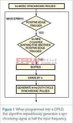
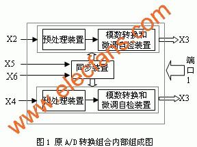
图1所示为等占空比发生器的算法。CPLD首先等待正边沿触发,然后开始以60MHz的频率计数,等待下一个正边沿触发。当下一个正边沿到来时,同步信号的周期计数完成。计数值随即被储存到缓冲器,除以2得到等占空比发生器的值。
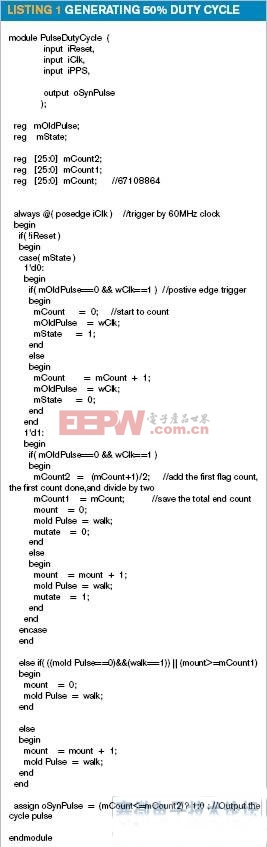
测试中,本设计方案等占空比发生器的频率范围覆盖2Hz到450kHz。不仅可以用于脉冲发生器,还可以用于同步对其他系统触发过窄的脉冲信号。等占空比发生器适合CPLD,例如带60MHz系统时钟和MM74HCT244缓冲器、输出TTL信号的Altera EPM570。表1为CPLD程序。
英文原文:
CPLD connects two instruments with half-duty-cycle generator
A clocking circuit programmed into a CPLD generates a synchronizing pulse for a slower instrument at half the duty cycle of a faster instrument.
Yu-Chieh Chen and Tai-Shan Liao, National Applied Research Laboratories, Hsinchu, Taiwan; Edited by Charles H Small and Fran Granville -- EDN, 10/11/2007
When synchronizing two instruments’ signals, it is important to make sure that the receiver can latch the sender’s synchronous signal. For example, a pulse generator generates synchronizing pulses while generating the main pulse signal. For the Avtek AV-1015B, the pulse generator’s duty cycle is approximately 50 nsec at TTL with a 50Ω load. The goal of this Design Idea is to increase the pulse generator’s high-level width to meet the triggering spec of a lock-in amplifier. The synchronizing pulse’s frequency is 10 Hz to 102 kHz, which is the lock-in amplifier’s frequency range.
.
Because the synchronizing pulse synchronizes to the main pulse, you must minimize any delay in calculating the lock-in amplifier’s synchronizing input. And, because the user can change the frequency of the pulse train from the pulse generator, the synchronizing signal’s frequency also changes. Therefore, you must make sure that the circuit properly calculates and generates the synchronizing signal, no matter how the user sets the output of the pulse generator.
Figure 1 shows the half-duty-cycle generator’s algorithm. The CPLD first waits for the positive-edge trigger, then starts to count at a frequency of 60 MHz, and waits for the next positive-edge trigger. When the next positive edge comes, the synchronizing signal’s period counting is complete. The counting value then gets saved in a buffer and divided by 2 to yield the value for half-duty-cycle generation.
In tests, the half-duty-cycle ge
nerator in this Design Idea worked over a frequency range of 2 Hz to 450 kHz. You can use this design not only in a pulse generator, but also in any synchronizing signal in which the pulse is too narrow for other system triggering. The half-duty-cycle generator fits into a CPLD, such as an Altera EPM570 with a 60-MHz system clock and an MM74HCT244 buffer to output a TTL signal. Listing 1 contains the program for the CPLD.


评论