ADC的SNR:位数到底去那了?

理论上,一个ADC的SNR(信号与噪声的比值)等于(6.02N+1.76)dB,这里N等于ADC的位数。虽然我的数学技巧有点生疏,但我认为任何一个16位转换器的信噪比应该是98.08dB。但当我查看模数转换器 的数据手册时,我看到一些不同的情况。比如,16位的(逐次逼近型)模数转换器指标的典型值通常可低至84dB高达95dB。生产厂家很自豪地把这些值写 在产品的数据手册的首页,而且坦率地说,信噪比为95dB的16位ADC具有竞争力。除非我错了,计算的98.08dB高于所找到最好的16位ADC数据 手册中的96dB。那么,这些位数到那去了?
本文引用地址:https://www.eepw.com.cn/article/186081.htm 让我们先找出理想化的公式(6.02N+1.76)从何而来。任何系统的信噪比,用分贝来表示的话,等于20log10(信号的均方根/噪音的均方根)。推导出理想的信噪比公式时,首先定义信号的均方根。如果把信号的峰峰值转换为均方根,则除以![]() 即可。ADC的均方根信号用位数表示等于
即可。ADC的均方根信号用位数表示等于![]() ,这里q是LSB(最低有效位)。
,这里q是LSB(最低有效位)。
所有ADC产生量化噪声是把输入信号抽样成离散“桶”的后果。这些桶的理想宽度等于转换器LSB的大小。任何ADC位的不确定值是±1/2 LSB
。如果假定对应每个位误差的响应是三角形的话,则其均方根等于LSB信号的幅值除以![]() ,均方根的噪声则
,均方根的噪声则![]() 。
。
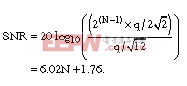
综合均方根和均方根噪声条件,理想ADC的SNR用分贝表示为:
重复刚才的问题,那些位数到底去那了? 那些ADC的供应商热情地解释这个失位现象,因为他们的众多试验装置表明产品具有良好的信噪比。从根本上说,他们认为电阻和晶体管的噪声导致了这种结果。供应商测试其ADC的SNR是通过将他们的数据带入下面的公式:
![]()
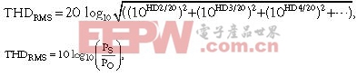
这些理论和测试SNR的公式是完善的,但他们只能提供部分你需要知道的转换器到底能给予你的位数。THD (总谐波失真),另一个要注意的ADC指标,定义为谐波成分的均方根和,或者是输入信号功率的比值
 或者
或者
这里HDx是x次谐波失真谐波的幅值,PS是一次谐波的信号功率,Po是二次到八次谐波的功率。ADC的重要指标,INL(积分非线性)误差清晰地出现在THD结果中。
最后,SINAD(信号与噪声+失真比)定义为信号基波输入的RMS值与在半采样频率之下其它谐波成分RMS值之和的比值,但不包括直流信号。对 SAR和流水线型而言,SINAD的理论最小值等于理想的信噪比,或6.02N+1.76dB。至于Δ-Σ转换器的理想SINAD等于 (6.02N+1.76dB+![]() ,其中fS是转换器采样频率,BW是感兴趣的最大带宽。非理想SINAD值为
,其中fS是转换器采样频率,BW是感兴趣的最大带宽。非理想SINAD值为![]() 或者
或者![]()
其中PS是基波信号功率,PN是所有噪声谱成分的功率,PD是失真谱成分功率。
因此,下一次当你寻找丢失的位数时,记住它是结合了SNR、THD和SINAD等多个指标,这些可以让您全面了解ADC的真实位数--无论它采用的是逐次逼近型、流水线型还是Δ-Σ技术,不管在数据手册的第一页中提到有多少位。
附英文原文:
SNR in ADCs: Where did all the bits go?
Theoretically, the SNR for any 16-bit converter should be 98.08 dB. But I see something different when I read converter data sheets.
By Bonnie Baker -- EDN, 6/7/2007
Theoretically, the SNR (signal-to-noise ratio) of an ADC is equal to (6.02N+1.76) dB, where N equals the number of ADC bits. Although I’m a little rusty with my algebra skills, I think that the SNR for any 16-bit converter should be 98.08 dB. However, I see something different when I read converter data sheets. For instance, the specification for a 16-bit SAR (successive-approximation-register) converter can typically be as low as 84 dB and as high as 95 dB. Manufacturers proudly advertise these values on the front page of their data sheets, and, frankly, an SNR of 95 dB for a 16-bit SAR converter is competitive. Unless I am wrong, the 98.08 dB I calculate is higher than the 95-dB specification that I find with the best of the 16-bit-converter data sheets. So, where did the bits go?
Let’s start by finding out where this ideal formula, 6.02N+1.76, comes from. The SNR of any system, in decibels, is equal to 20 log10 (rms signal/rms noise). When you d
erive the ideal SNR formula, you first define the rms signal. If you change a peak-to-peak signal to rms, you divide it by the ![]() The ADC rms signal in bits is equal
The ADC rms signal in bits is equal ![]() where q is the LSB (least-significant bit).
where q is the LSB (least-significant bit).
All ADCs generate quantization noise as a consequence of dividing the input signal into discrete “buckets.” The ideal width of these buckets is equal to the converter’s LSB size. The uncertainty of any ADC bit is ±1/2 LSB. If you assume that this error’s response is triangular across each bit, the rms value equals this LSB signal’s magnitude divided by![]() :rms noise
:rms noise![]()
Combining the rms-signal and rms-noise terms, the ideal ADC SNR in decibels is:
Again, where did the bits go? The ADC vendors enthusiastically explain the missing-bits phenomenon, because they bench-test their devices to see how good the SNR is. Fundamentally, they find that the device noise from resistors and transistors creeps into the results. Vendors test their ADC SNR by inputting their data into the following formula:
![]()
These theoretical and tested SNR formulas are complete, but they provide only part of what you need to know about how many bits your converter is truly giving you. THD (total harmonic distortion), another ADC specification you need to watch, is the ratio of the rms sum of the powers of the harmonic components, or spurs, to the input-signal power:
or
where HDx is the magnitude of distortion at the Xth harmonic, PS is the signal power of the first harmonic, and PO is the power of harmonics two through eight. Significant ADC INL (integral-nonlinearity) errors typically appear in the THD results.
Finally, SINAD (signal-to-noise and distortion) is the ratio of the fundamental input signal’s rms amplitude to the rms sum of all other spectral components below half of the sampling frequency, excluding dc. The theoretical minimum for SINAD is equal to the ideal SNR, or 6.02N+1.76 dB, with SAR and pipeline converters. For delta-sigma converters, the ideal SINAD equals 6.02N+1.76 dB+10 log10(fS/(2BW)), where fS is the converter sampling frequency and BW is the maximum bandwidth of interest. The not-so-ideal value of SINAD is ![]() or
or![]() .
.
where PS is the fundamental signal power, PN is the power of all the noise spectral components, and PD is the power of all the distortion spectral components.
So, the next time you’re looking for lost bits, remember that it is the combination of SNR, THD, and SINAD that gives you the complete picture of the real bits in your ADC—regardless of whether it’s SAR, pipeline, or delta-sigma technology and regardless of the number of bits that the first page of the data sheet mentions.


评论