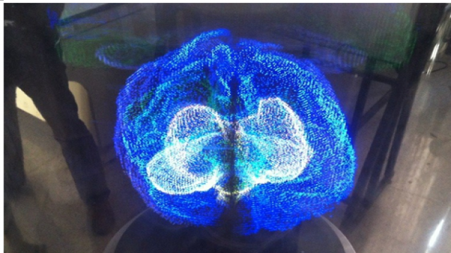
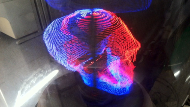
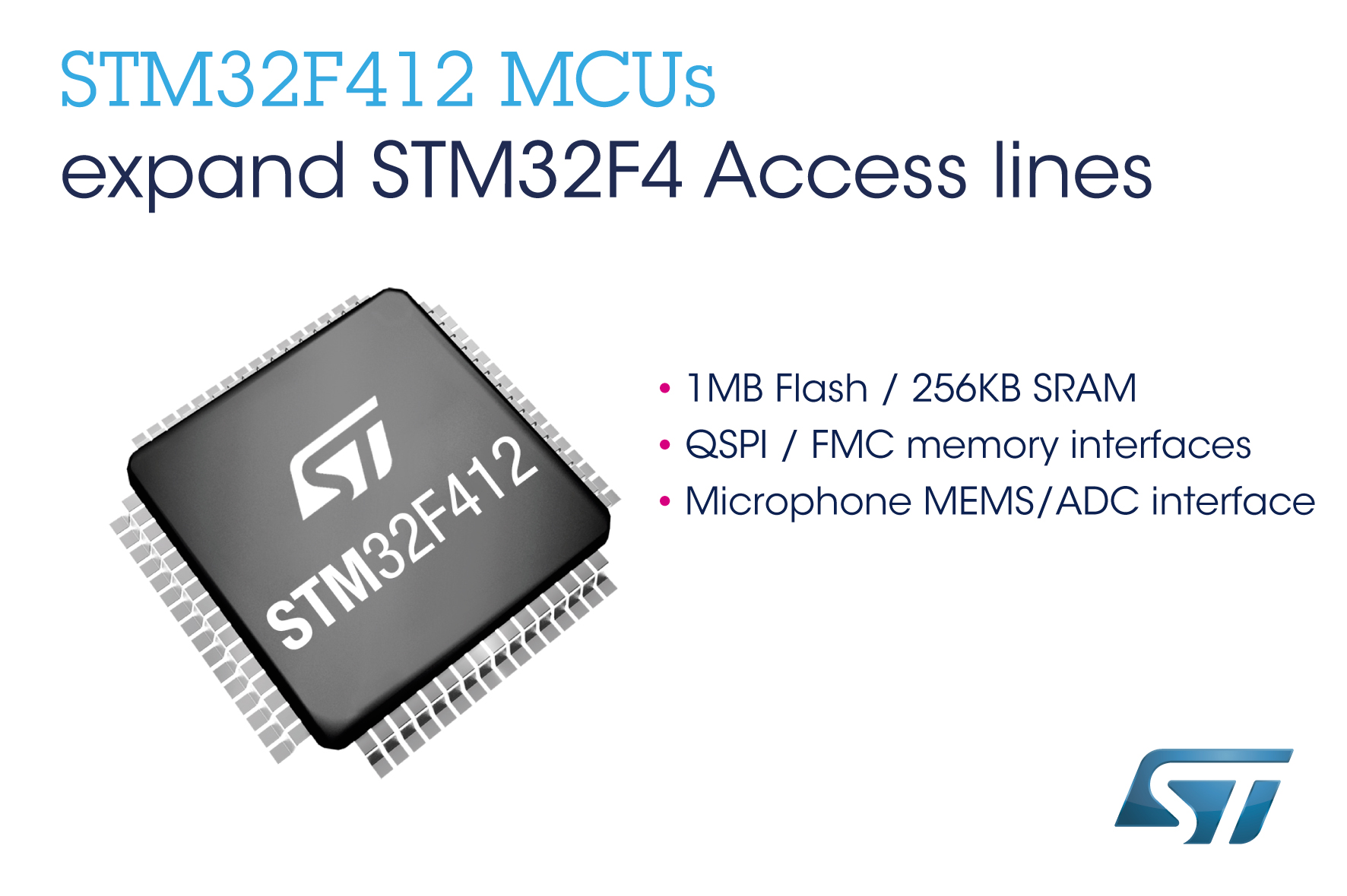
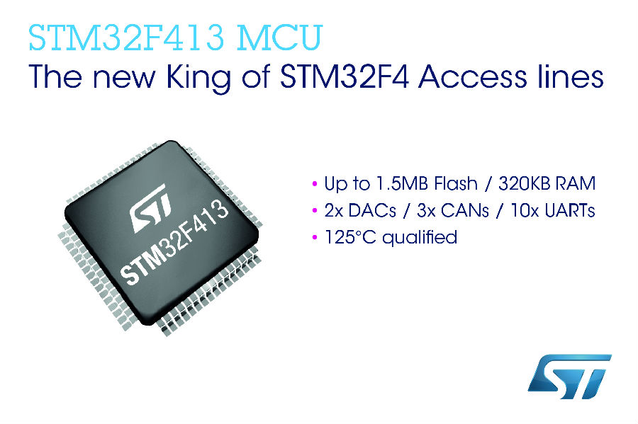
基于stm32f4的三维旋转显示平台
3.系统软件设计
本文引用地址:http://www.eepw.com.cn/article/201609/296520.htm3.1软件控制流程:

3.2关于实时生成体三维显示数据的讨论:
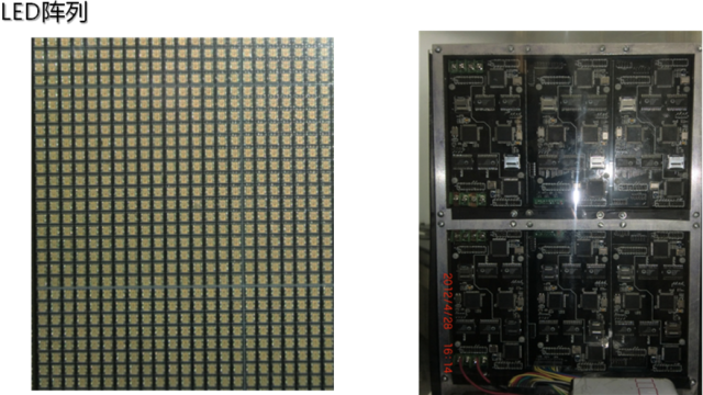
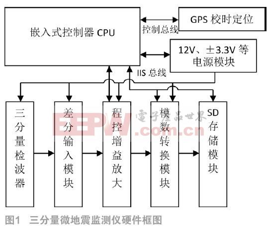
一个瓦片64*32
LED层FPGA*8:每个16*16LED
中间层stm32*2:每个4LED层的FPGA,也即32*32
由于经过压缩,一个led数据为4bits
所以一个stm32每一帧所要生成的数据为32*32*0.5bytes = 512bytes
转速800转,一帧1/800s = 1.25ms = 1250000ns
stm32f4主频168Mhz,指令周期 = 5.93ns
约可执行20万多条指令
假设fsmc总线的速度为50Mhz,则每帧写入的时间大概在0.02ms内
程序总体思路
事先算出所有电子帧上非零的点,以及连续0的个数,在每一个电子帧同步后,算出生成下一帧的数据,写入fifo
输入:线段端点的集合
//input: endpoints of segments which formed the outline of a 3D model
//x position with range 0-95
//y position with range 0-95
//z position with range 0-128
/******************************************/
//from later discussion, one of the Q format
//type should replace the char type
/******************************************/
struct Coordinate_3D
{
_iq xPosition;
_iq yPosition;
_iq zPosition;
};
//after you get the intersection points in 3d coordinate, you need to remap it into 2d coordinate on the very electrical plane,
//and the conversion is quite simple Coordinate_2D.yPosition = Coordinate_3D.zPosition; Coordinate_2D.xPosition = sqrt(xPosition^2+yPosition^2)
struct Coordinate_2D
{
char xPosition;
char yPosition;
};
struct Line
{
struct Coordinate_3D beginPoint;
struct Coordinate_3D endPoint;
unsigned char color;
};
//frame structure to store the visible points in one electrical frame
//need to be discussed
//here's the prototype of the Frame structure, and basically the frame struture should contain the visible points,
//and the zero points. As we have enclosed the number of zero points after each visible points in their own data structure,
//only the number of zero points at the beginning of the whole frame should be enclosed in the frame struture
struct Frame
{
int zerosBefore;
PointQueue_t visiblePointQueue;
};
//we need a union structure like color plane with bit fields to store the color imformation of every four FPGAs in one data segment
//actually, it's a kind of frustrateing thing that we had to rebind the data into such an odd form.
union ColorPalette
{
struct
{
unsigned char color1 : 4;
unsigned char color2 : 4;
unsigned char color3 : 4;
unsigned char color3 : 4;
}distributedColor;
unsigned short unionColor;
};
//and now we need a complete point structure to sotre all the imformation above
//here we add a weight field = yPosition*96 + xPosition, which will facilitate
//our sort and calculation of the zero points number between each visible point
//it's important to understand that, 4 corresponding points on the LED panel
//will share one visiblepoint data structure.(一块stm32负责4块16*16的LED,每块对应的点的4位颜色信息,拼成16位的数据段)
struct VisiblePoint
{
struct Coordinate_2D coord;
union Colorplane ColorPalette;
int weight;
int zerosAfter;
};
//as now you can see, we need some thing to store the visible points array
typedef struct QueueNode
{
struct VisiblePoint pointData;
struct QueueNode * nextNode;
}QueueNode_t, *QueueNode_ptr;
typedef struct
{
QueueNode_ptr front;
QueueNode_ptr rear;
}PointQueue_t;
//finally, we will have 16*16 words(16 bits)to write into the fifo after each electrial frame sync cmd.
//it may hard for us to decide the frame structure now, let's see how will the work flow of the algorithm be.
//firstly, the overall function will be like this
void Real3DExt(struct Line inputLines[], int lineNumber, struct Frame outputFrames[])
//then we need some real implementation function to calculate the intersection points
//with 0 = no intersection points, 1 = only have one intersection points, 2 = the input line coincides the given electrical plane
//2 need to be treated as an exception
//the range of the degree is 0-359
//it's important to mention that each intersection point we calculate, we need to
//remap its coordinate from a 32*32 field to x,y = 0-15, as each stm32 only have a 32*32
//effective field(those intersection points out of this range belong to other stm32), which can be decided by its address
int InterCal(struct Line inputLine, struct VisiblePoint * outputPoint, int degree)
//so we will need something like this in the Real3DExt function:
for (int j = 0; j < 360; j++)
{
for(int i = 0; i < lineNumber; i++ )
InterCal(struct Line inputLine, struct VisiblePoint outputPoint, int degree);
......
}
/******************************************/
//simple float format version of InterCal
/******************************************/
//calculate formula
//Q = [-1,1,-1];
//P = [1,1,-1];
//V = Q - p = [-2,0,0];
//Theta = pi/6;
//Tmp0 = Q(1)*sin(Theta) - Q(2)*cos(Theta);
//Tmp1 = V(1)*sin(Theta) - V(2)*cos(Theta);
//Result = Q - (Tmp0/Tmp1)*V
float32_t f32_point0[3] = {-1.0f,1.0f,-1.0f};
float32_t f32_point1[3] = {1.0f,1.0f,-1.0f};
float32_t f32_directionVector[3], f32_normalVector[3], f32_theta,
f32_tmp0, f32_tmp1, f32_tmp2, f32_result[3];
arm_sub_f32(f32_point0,f32_point1,f32_directionVector,3);
f32_theta = PI/6.0f;
f32_normalVector[0] = arm_sin_f32(f32_theta);
f32_normalVector[1] = arm_cos_f32(f32_theta);
f32_normalVector[2] = 0.0f;
arm_dot_prod_f32(f32_point0, f32_normalVector, 3, &f32_tmp0);
arm_dot_prod_f32(f32_directionVector, f32_normalVector, 3, &f32_tmp1);
f32_tmp2 = f32_tmp0/f32_tmp1;
arm_scale_f32(f32_normalVector, f32_tmp2, f32_normalVector, 3);
arm_sub_f32(f32_point0, f32_normalVector, f32_result, 3);
//and than we need to decide whether to add a new visible point in the point queue, or to update
//the color field of a given point in the point queue(as 4 visible point share one data structure). from this point, you will find that, it may be
//sensible for you not to diretly insert a new point into the end of point queue but to insert it in order
//when you build the pointqueue. it seems more effective.
void EnPointQueue(PointQueue_t * inputQueue, QueueNode_t inputNode);
//finally we will get an sorted queue at the end of the inner for loop
//than we need to calculate the number of invisible points between these visible points
//and to store it in each frame structure. the main purpose to do so is to offer an quick generation
//of the blank point(color field = 16'b0) between each electrical frame
//the work flow will be like this:
loop
{
dma output of the blank points;
output of the visible points;
}
/******************************************/
//some points need more detailed discussion
/******************************************/
//1.memory allocation strategy
//a quite straight forward method will be establishing a big memnory pool in advance, but the drawback of this method
//is that it's hard for you to decide the size of the memory pool. Another way would be the C runtime library method,
// and you can use build-in function malloc to allocate the memory, but it will be a quite heavy load for the m3 cpu
// as you need dynamic memeory allocation throughout the algorithm.
//2.the choice of Q format of the IQMATH library
//from the discussion above, the range of the coordnate is about 1-100, but the range of sin&cos is only 0-1,so there's a large gap between them.
//may be we can choose iq24?? Simultaneously, another big problem will be the choice between IQMATH and arm dsp library as their q format is
//incompatible with each other. as far as my knowledge is concerned, we should choose IQMATH with m3 without fpu, and cmsis dsp library with m4 with fpu.
//more detail discussion about the range of the algorithm
//x,y range is -64 to 64
//the formula is
//Tmp0 = Q(1)*sin(Theta) - Q(2)*cos(Theta);
//Tmp0 range is -128 to 128
//Tmp1 = V(1)*sin(Theta) - V(2)*cos(Theta);
//Tmp1 range is -128 to 128
//Result = Q - (Tmp1/Tmp2)*V
//because the minimal precision of the coordinate is 1, so if the result of Tmp1/Tmp2 is bigger than 128, the Result will be
//saturated. With the same reson, if (Tmp1/Tmp2)*V >= 128 or <= -127, the result will be saturated
4.系统创新
其一,由于高效解析算法的提出,大幅简化了真三维显示器显示数据的获取难度,只需在PC端获得当前较为标准化的三维图形的三角面顶点数据流文件,即可在真三维显示平台上显示出来,使得真三维显示器的整体显示流程大为简化。
其二,由于显示体的结构分为并行的若干区块,各个区块只显示自身的部分,因此显示屏幕的扩大并不会造成数据计算量的大幅增加,这就使得本显示器的扩展性大大增强,可以适用于多种多样的显示范围与领域。
其三,由于高效算法的优化与区块化显示的优势,并行结构的计算量相对较少,这就使得实时控制得以实现,大大增强了真三维显示器的应用领域。
其四,高效算法与区块化显示使得本三维体显示器不需要如国内外其他同类产品的中所需的高速传输方式,因此大大减少了从产品研发到材料再到加工中各个环节的成本。
5.评测与结论
在作品的过程中,我们发现本作品虽然还不是很成熟,也同样具备较大的应用前景与价值。价格成本的极大降低,使得真三维立体显示的门槛很低,那么在一些对清晰度要求不高,但是希望多层次全角度呈现三维图像的应用领域,我们的真三维立体显示器能发挥较大的作用。
附录


评论