PSoC CY8C21x23血压监测方案能替代传统系统元件
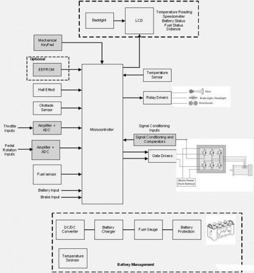
This system includes the following blocks:
Pressure sensor
Amplifier
Filter
Multiplexer and ADC
Heart rate timer
Safety timer
Pneumatics
Display
图2. PSoC血压方框图
PSoC血压计主要元件:
1. Pressure Sensor
The pressure sensor for blood pressure monitoring system should have the following characteristics:
Measure pressures from 0 mmHG (0 Kpa) to 300 mmHg (40 Kpa).
Gauge type, because blood pressure in relation to atmospheric pressure
MPX2053 (piezoresistive pressure sensor from Free scale) is used in this example. It gives differential output with maximum measurable pressure range of 50 Kpa. It has a transfer characteristic of (20 mV/50 Kpa) 0.4 mv for every 1 Kpa change in pressure or 53 μV per mmHG with Vs=5V.
2. Amplifier
The sensor output is in the order of a few mega volts. Three opamp topology instrumentation amplifier is used to amplify the pressure signal. It provides a gain of 93.
Gain = Diff Gain * Conversion Gain = 48 * 1.98 = 93
3. Filter
The sensor output consists of two signals: cuff pressure signal and oscillometric signal. The oscillometric signal has frequency components between 0.3 Hz to 20 Hz. Two stage filters are used to filter out the oscillometric pulses.
4. First Stage
A high gain AC filter, described in the Cypress application note AN2320 is implemented in the first stage.
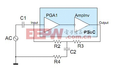
图3.高AC 增益放大器电路
The filter’s cutoff is set around 1 Hz. This filter removes all DC components and gives the AC signal a sufficient gain. The output of the first stage has unwanted high frequency components.
5. Second Stage
High frequency components are removed using two pole low pass filters implemented inside PSoC. This filter is constructed using two switched capacitor blocks. The filter’s cutoff is set at 50 Hz with a 0 dB gain.
6. Multiplexer and ADC
DC Pressure signal and the oscillometric are multiplexed to ADC inside the PSoC. The MUX selects one of these signals to a 13-bit incremental ADC, which runs at a sampling rate of 30 samples/second.
7. Heart Rate Timer
A 24-bit timer is used to calculate the heart rate. Timer is clocked using a source of frequency 62.5 kHz. The period value is set to 500000 to deliver an output of 4 seconds. Heart rate is calculated by capturing the timer period at oscillometric pulse triggers.
Start the four second window timer
Capture the timer’s period value when oscillometric pulses crosses the defined threshold
Record timer value for four such crossings

8. Safety Timer
This timer generates an interrupt every four seconds and checks if the cuff pressure is above specific threshold for that time window. (AAMI safety standards defines the maximum time limit for holding a particular pressure at arm cuff.) If the pressure in the cuff exceeds the safety pressure level then the solenoid valve is opened to deflate the cuff completely.
9. Pneumatics
Pneumatics forms the main part of any blood pressure monitoring system. Pneumatics of a typical monitor has the following:
Cuff
Air chamber
Rolling pump
Solenoid valve
The cuff is worn around the upper arm; it detects the change in pressure due to pulsation of artery. Cuff is connected to pressure sensor through air chamber, which in turn connects to the solenoid valve and rolling pump. Rolling pump inflates the cuff. Solenoid valve deflates the cuff at a defined rate .Usually the deflation rate is lowered if more samples of oscillometric pulses are needed and vice versa. Figure 5 shows the pneumatics setup used to build a typical blood pressure monitor.
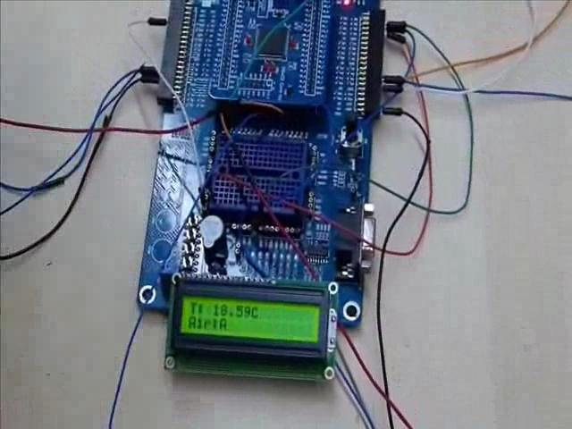
10. Display
A 16x2 character LCD is used to display the results Using RS232 communication, the. oscillometric pulses are recorded with reference to pressure in cuff. Figure 6 shows the oscillometric pulses and pressure in cuff recorded during deflation.
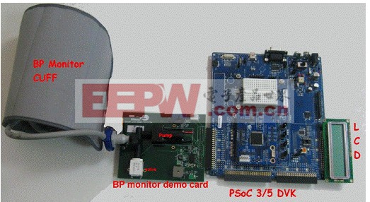
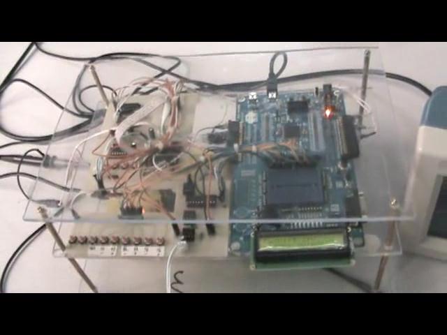
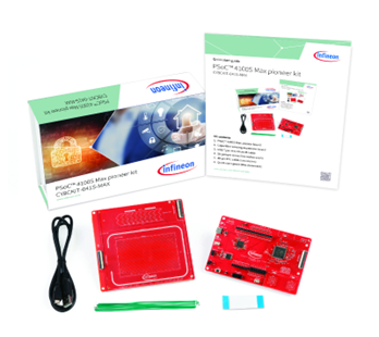
图4.PSoC血压计外形图
更多医疗电子信息请关注:21ic医疗电子频道


评论