灯光控制系统电路
It is easy to install a couple of infrared emitter and receiver at the entrance of your room and maybe you connect them to the light, but you cannot control the light in this way! You will never know how many person inside and if the room is empty or not. In this system, every thing is under control, because it is smart enough to know how many persons inside; and it can identify the direction of them, so the light will be turned OFF when the room is unoccupied; and ON otherwise! This tutorial will show you how.
Theorem of Operation:
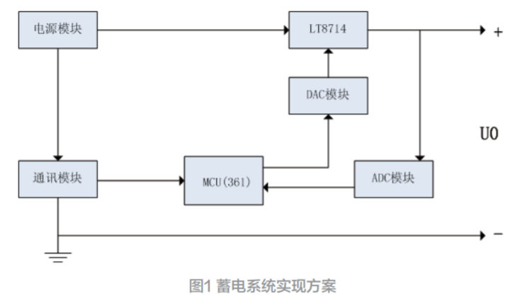
As shown in Figure 1, Light Control System has five units:
1- Power supply to convert 240V AC into 5V DC.
2- Sensing units that convert body motion into analogue electrical signals.
3- Analogue comparator to convert analogue signals into digital signals.
4- Microcontroller to process these digital signals and send the appropriate command to the room light.
5- Relay to act as an interface between low voltage (control system and sensors) high voltage (room light).
Sensing unit consists of infrared emitter OP295 to produce the infrared beam, two detectors in front of the emitter to detect the infrared beam OP598. Since the main idea in this device is to know person direction; and so, to get this approach, we have to use tow pieces of infrared detector in order to
| A Detectror | B Detector | |
1 | High | High |
2 | Low | High |
3 | Low | Low |
4 | High | Low |
5 | High | High |
| Tip: |
| If you have a camcorder, or just a camera mobile phone, you can see the infrared light! Just point the infrared emitter at the camera then you will be able to see the infrared light in the viewfinder. If you point your remote at the camera and push a button, you will see flashing light! |
identify the direction of the person as shown in Fig 2.
When Infrared beam become broken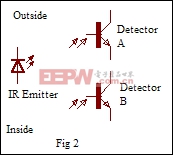 due to any body, the output signals from these detectors will be changed in unique sequence. Controller will identify the direction of the person by analyzing these signals as shown in the table at right from 1 to 5 passed IN, 5 to 1 passed OUT:
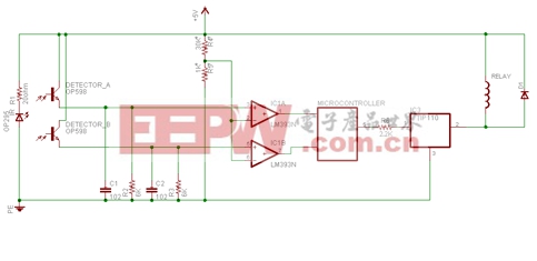
Since detectors output signals are analogue while the controller can only process digital signals, these signals must be converted to digital through the analogue comparator LM393.
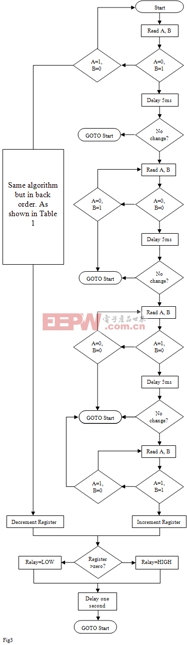
Controller will increase the number of the persons in side the room by one, or decrease it by one when the appropriate sequence of signals have occurred. If this number is greater than zero, light will be turned on otherwise it turned off.
After this, controller will stop scan sensors for one second to allow the whole body to pass. Fig 3 describe the whole algorithm
Sensors circuit is so sensitive in Light Control System, that mean any external noise or any small variation in voltage will change the sensors circuit status. While these signals are changing due to these reasons, microcontroller will assume that some one pass in front of sensor and so a fault will occur. In order to solve this problem I have used soft and hard components capacitors to make Light Control System stable as much as possible. A soft component is an algorithm in the control code to separate the noises signals from the real signals.
Notes:
- You have to isolate detectors from any kind of light, except the infrared radiation.
- Use TIP110 to drive relay current; it has Base-Emitter Shunt Resistors built in. Diode D1 is acting as a freewheeling diode.
- Analogue reference voltage should be less than voltage produced by the detectors; otherwise, the system will not function properly . Less than 0.1V is recommended
- The maximum speed of the body to be detected by the Light control System is 1.67 metersecond = 0.462 KmHour this value is accurate only if the depth of the passing body in front of sensors is equal to the distance between these two infrared receiver, if this depth is more, the maximum speed will be increased.
- Light Control System is unable to detect any body with a depth less than the distance between 2 receiver.
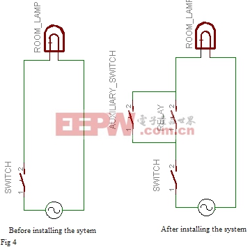
- By adding an auxiliary switch, Light Control System can be disabled if any failure has occurred after installing. This auxiliary switch disables the functionality of Light Control System and restores the wall light switch to the previous state as shown in figure 4.

DIY机械键盘相关社区:机械键盘DIY


评论