Freescale MC56F8257数字信号控制器开发方案
• Clock sources
— On-chip relaxation oscillator with two user selectable frequencies: 400 kHz for low speed mode, 8 MHz for normal operation
— External clock: crystal oscillator, ceramic resonator, and external clock source
• Cyclic Redundancy Check (CRC) Generator
— Hardware CRC generator circuit using 16-bit shift register
— CRC16-CCITT compliancy with x16 + x12 + x5 + 1 polynomial
— Error detection for all single, double, odd, and most multi-bit errors
— Programmable initial seed value
— High-speed hardware CRC calculation
— Optional feature to transpose input data and CRC result via transpose register, required on applications where bytes are in LSb (Least Significant bit) format.
• Up to 54 general-purpose I/O (GPIO) pins
— 5 V tolerant I/O
— Individual control for each pin to be in peripheral or GPIO mode
Individual input/output direction control for each pin in GPIO mode
— Individual control for each output pin to be in push-pull mode or open-drain mode
— Hysteresis and configurable pullup device on all input pins
— Ability to generate interrupt with programmable rising or falling edge and software interrupt
— Configurable drive strength: 4 mA / 8 mA sink/source current
• JTAG/EOnCE debug programming interface for real-time debugging
IEEE 1149.1 Joint Test Action Group (JTAG) interface
EOnCE interface for real-time debugging
Power Saving Features
• Low-speed run, wait, and stop modes: as low as 781 Hz clock provided by OCCS and internal ROSC
• Large regulator standby mode available for reducing power consumption at low-speed mode
• Less than 30 μs typical wakeup time from stop modes
• Each peripheral can be individually disabled to save power
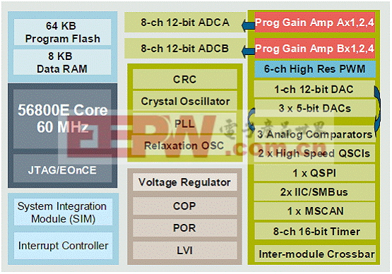
图1.MC56F825x方框图
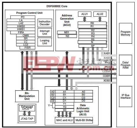
图2.56800E核框图
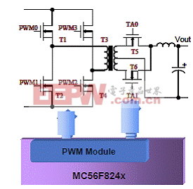
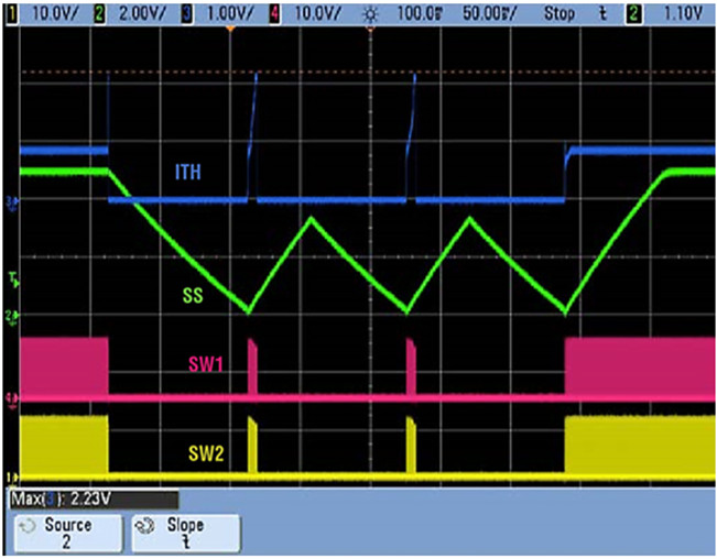
图3.MC56F824x相移电源转换器框图
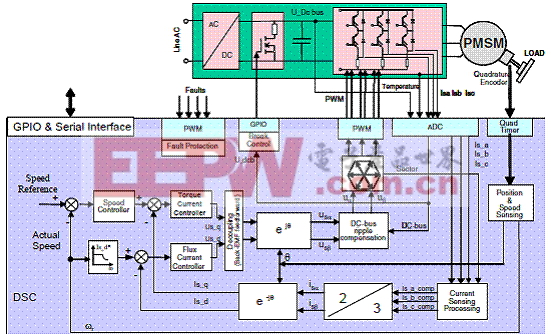
图4.MC56F825x高性能PMSM伺服系统框图
TWR-56F8257: MC56F8257 Tower MCU模块
The MC56F8257 Tower MCU module (TWR-56F8257) is a cost-effective evaluation, demonstration and development board. The TWR-56F8257 can operate stand-alone or as the main control board in a Tower System with peripheral modules. It can also be used as the main control board with an APMOTOR56F8000E motor control board.
TWR-56F8257主要特性:
The following list summarizes the features of the TWR-56F8257:
• Tower-compatible microcontroller module
• Selectable power sources:
USB
Barrel connector
Motor control board
Tower elevator board
• Filtered power for VDDA and VSSA on the MC56F8257DSC
• MC56F8257 digital signal controller (DSC) in an 64 LQFP package
• Optional 8 MHz crystal circuit for the MC56F8257 DSC
• Nine LEDs controlled by the MC56F8257 DSC
• Motor control board connector for the APMOTOR56F8000E motor control board
• Auxiliary signal connector
• Four thermistors for single-ended or differential analog inputs to the MC56F8257 DSC
• CAN transceiver, header and termination
• Two push buttons for user input or interrupts to the MC56F8257 DSC
• Reset push button for the MC56F8257 DSC
• JTAG header for the MC56F8257 DSC with header to disconnect from OSBDM
• Headers to connect SCI signals to either USB bridge or elevator board
• Expansion via primary elevator connector
• MC9S08JM60 MCU with a 4 MHz crystal provides:
Open source debug (OSBDM) circuit
USB to SCI bridge
Header to select between OSBDM and USB to SCI bridge functions
Bootloader enable header
BDM header for the MC9S08JM60 MCU
Status and target power indicator LEDs
Control of semiconductor switch to enable power to board from USB
Voltage translators between 5V MC9S08JM60 MCU chip and 3.3V MC56F8257 DSC chip

图5.TWR-56F8257框图


评论